Solar Powered Weather Data Collection

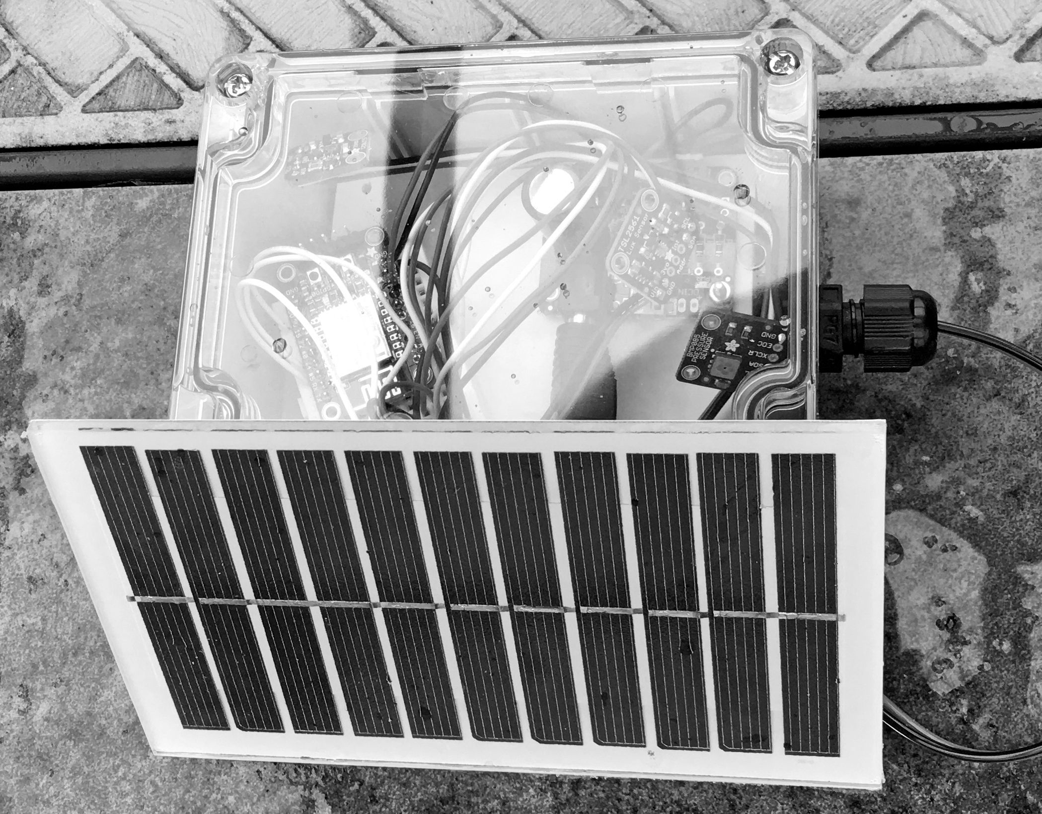
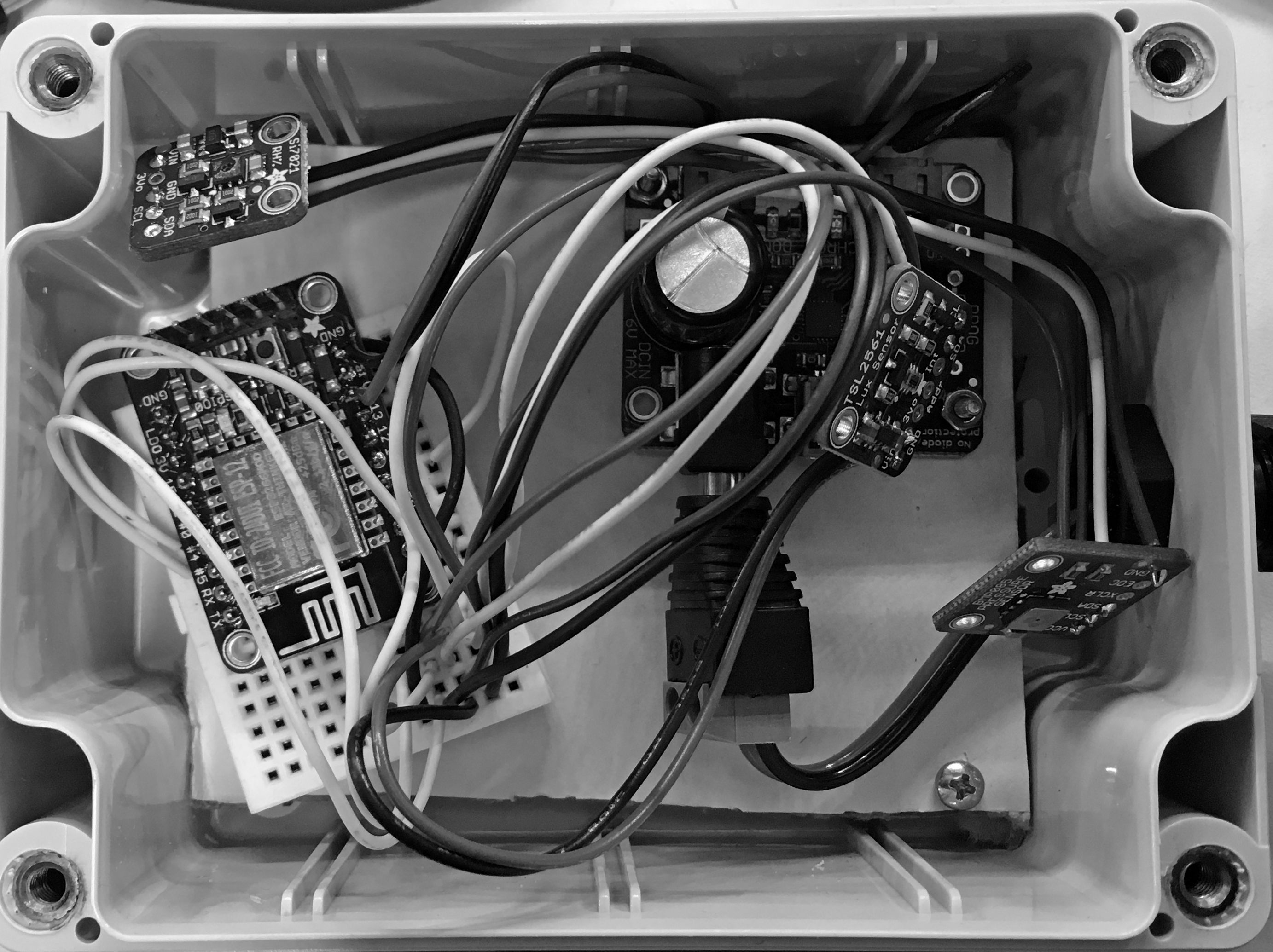
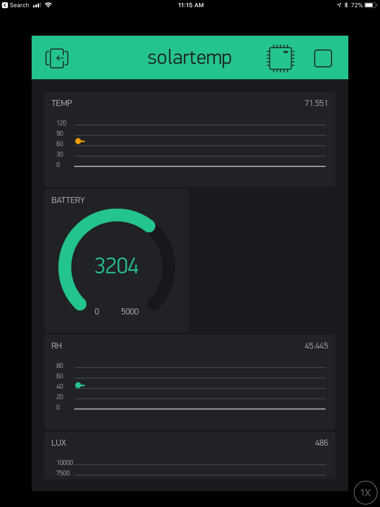
For a while I’ve wanted a system that can report weather data and be solar powered. The ESP8266 is an cheap choice, and this is my first experience using Blynk. The prototype was a weekend project that just needed some assembly. It’s entirely built from Adafruit modules. The EPS8266 is put into deep sleep for 60 seconds…even that may be too frequent. The downside of using the EPS8266 deep sleep mode with Blynk: Blynk often reports the device as offline. I think this is because it can’t do a pull. The EPS8266 wakes up, pushes data, then goes back to sleep.

All the sensors are I2C based. The standard Arduino libraries work right out of the box. If the prototype works well, I might create a pcb that glues everything together.

I’m using the following Adafruit boards:

  • BMP086 pressure sensor
  • TSL2561 lux sensor
  • si7021 RH sensor
  • ESP8266 Huzzah
  • Solar Lion charger #390

esp8266_weather1_edit

esp8266_weather2_edit

eps8266_blink

Build Log: Bitx40 in the Case

I’ve had the surface mount (nearly assembled) version of the Bitx40 in a box since late last year. Its been a struggle to find a case that some room for expansion, but can still be used in the field. I settled on a Hammond 1598CSGY. The case is “instrument” style and has removable (and replaceable) front and rear aluminum panels.

My modifications to this so far are:

  • Rear BNC antenna connector
  • Anderson PowerPole connector
  • Upgraded heatsink
  • Bourns 10K potentiometer for volume control
  • Toggle switch for power
  • Nine pin Kenwood connector for the mic

I’ve verified the analog VFO works. It is too touchy without a geared or ten-turn potentiometer to control the frequency. I’m going to use my own DDS system. Probably built on an Atmel ARM and Si5351.

bitx0 copy bitx0

Build Log: Final Install of the MiniKits RF Amplifier

After the pcb was finished (minus the power MOSFET), the heat sink needs to be drilled and tapped for to mount the standoffs and the MOSFET pair. Source a 150x80mm heatsink on Amazn. The bottom is at least a quarter inch thick. I’m using M3-0.5 standoffs for all pcb mounting. It’s actually pretty hard to find a 2.5mm drill bit. I tried a metric tap set from Dubro, but snapped the bit in the first minute. I ended up purchasing a 40 pack (cheap imported bits). These bits performed way better.

minikits amp edit minikits amp side edit

Bourns Optical Rotary Encoder Final Assembly

The new circuit boards for the break-out board I designed arrived. The assembled version checks out just fine with the interrupts enabled using the PJRC Encoder library.

I’ve struggled finding the perfect tuning knob to use this encoder on my [ongoing] M1 Transceiver build. Eventually, I decided the best thing to do would be to buy another Elecraft K3 tuner knob directly. Bottom picture shows it perfectly.


bourns rotary encoder back


bourns rotary encoder front


bourns rotary encoder mounted


Build Log: Automated Barn Door Star Tracker Part 2

I made progress on the barn door star tracker. A few weeks ago I got the switches debounced (in software). I put labels on the control box. The control box hangs on the bottom of the platform. It’s attached at one side for easy access. The control box has the two switches and an LED mounted on it. Inside the box is an EasyDriver and a Teensy 3.1. The batteries won’t fit in the box, so I mounted them on the other end of the platform.

I’ve written enough of the software to get the reset “program” working. If you click the momentary switch towards reset, then it will lower the platform until the limit switch is triggered. I’ve got the “run” program sketched out so I know the motors will move. The next step is to measure the actual speeds and introduce the math equation to make it the motor speed track the Earth’s rotation.


image1 copy


image2 copy


image3 copy

5V Boost Regulator

One of the building block projects I”m working on is a small boost regulator that can take a coin cell or two AAA’s and boost the voltage to 5V (or 3V with a part swap) for use with an AVR or Attiny (or your favorite mcu).

The NCP1402 series of boost regulator’s costs about $0.72 in single quantity. The NCP1402SN50T1G I’m using can  take a voltage as low as 1.8V and boost it to 5V at up to 200ma. The NCP1402 is a smd. This project also gives me an excuse to try using a new service from Digistump called pcbs.io. The photos below are prototype boards from pcbs.io


img_1037.jpg

Build Log: Automated Barn Door Star Tracker

My friend Jim Choate told me about his ideas around building an Arduino based barn door star tracker. I decided I could use one of these for some astro-photography out at The Cabin. After checking my parts bins, I found almost all the parts needed to build one. I set out with the goal of building a tracker with the least out of pocket costs.


I am reusing some MDF 3/4 inch board for the base and top. I drilled and tapped a piece of acrylic for the tripod mount on the bottom. This worked surprisingly well. I had to purchase a hinge at Home Depot. This is the largest source of “slop” in my implementation. The hinge is hard to mount such that the bottom and top “door” align when closed. I’m using the other hinge to anchor the stepper motor. I purchased a $13 lead screw off Amazon and a 5mm to 8mm shaft adapter. The camera mount is a ball head adapter for a tripod.

I have not wired this up yet. I’ve ordered a replacement shaft adapter. The one initially purchased has a spiral anti-backlash cut. It flexes dangerously when rotating the lead screw by hand. I predict it will break.


tracker1


tracker2


tracker mount

W7ZOI bi-directional RF amplifier PCB

It’s been a busy month. Sent two PCB designs out to Seeed in China for fabrication. The first one is a reproduction of W7ZOI’s IF amplifier circuit. This circuit is termination insensitive, and bi-directional. One could use two of these amplifiers, on each side of a crystal filter to reuse the it for transmit and receive. W7ZOI designed this as a contribution to the BITX transceiver aficionados. This is my own PCB design. I added SMA connectors and prototype space.


img_0908.jpg

Instrument for Measuring Absorbance 

I’ve been thinking about how to teach my kids quantifiable science.  I got a cheap science kit off Amazon for the kids a while back. The kit uses color changes to measure reactions using plant-based powders, but this is a binary outcome. It works or doesn’t. This is great for the first one or two experiments, but doesn’t really teach enduring principles, such as taking measurements, graphing, and ultimately forming to a conclusion.

The general idea behind measuring absorbance is to shine a light through a corvette (or test tube) and measure the amount of light that makes it through. Fancier instruments will use multiple wavelengths or an entire spectrum.

To keep this simple, I used a 3D printer to fabricate a holder for the test tubes from the science kit. A 635nm red LED shines in one side, and a BPW35 detects the light. The next step is to mount this on a small plastic project box with a cheap two line LCD display. A button (or two) will control taking measurements (and some kind of integrated calibration cycle).

This instrument will enable a simple number to be presented to the user. My kids can then perform reactions or dilute samples, and graph those numbers (math yeah).

absorbance instrument img_0880.jpg