My variation of the G3XBM’s 630m transverter arrived from pcbs.io. This is a surface mount version. Much to my surprise, the surface mount version reduces the parts cost significantly. Also note at the top of board, there are headers to replace the crystal oscillator with a DDS or alternate source.
New Gear: PreciseRF DPM6000 Power and SWR Meter
I wasn’t familiar with PreciseRF until I purchases a sampling coupler to use with my Rigol spectrum analyzer. I started browsing their catalog and they have some nice product offerings. A lab-grade power meter is something that has been missing from R&D bench for a while. The DPM6000 offers several detection methods. This will really keep the cost down for people who only work in HF, etc. The construction is nice, and they shipped my order same day.
My Customized BITX40 DDS Board
It’s been a pretty busy summer so far. The primary project on the BITX40. I decided to build my own DDS board for it. It’s based on an Atmel 328p, and has headers for the I2C OLED display, rotary encoder, and some extras. This board uses a Si5351A and has a five pole low pass filter on the output. This low pass filter nicely shapes the waveform into a Sine wave. There are some additional inputs if I want to add temperature, power, or SWR sensors.
As of this evening, I have the display, rotary encoder, and DDS output working together. More pictures to come. I have several of these boards that are spare. I’ll probably put the spares on my Tindie store.
Build Log: Bitx40 in the Case
I’ve had the surface mount (nearly assembled) version of the Bitx40 in a box since late last year. Its been a struggle to find a case that some room for expansion, but can still be used in the field. I settled on a Hammond 1598CSGY. The case is “instrument” style and has removable (and replaceable) front and rear aluminum panels.
My modifications to this so far are:
- Rear BNC antenna connector
- Anderson PowerPole connector
- Upgraded heatsink
- Bourns 10K potentiometer for volume control
- Toggle switch for power
- Nine pin Kenwood connector for the mic
I’ve verified the analog VFO works. It is too touchy without a geared or ten-turn potentiometer to control the frequency. I’m going to use my own DDS system. Probably built on an Atmel ARM and Si5351.
Build Log: Final Install of the MiniKits RF Amplifier
After the pcb was finished (minus the power MOSFET), the heat sink needs to be drilled and tapped for to mount the standoffs and the MOSFET pair. Source a 150x80mm heatsink on Amazn. The bottom is at least a quarter inch thick. I’m using M3-0.5 standoffs for all pcb mounting. It’s actually pretty hard to find a 2.5mm drill bit. I tried a metric tap set from Dubro, but snapped the bit in the first minute. I ended up purchasing a 40 pack (cheap imported bits). These bits performed way better.
Build Log: RF Final Power Amplifier for the M1 Transceiver
I’m doing a lot of product R&D on my bench, so the M1 took the back seat for a while. I broke out the RF power amplifier kit. The EME210 is based on the RDF16HHF1 mosfet. The power amp assembled for me in about three hours. There are only a few surface mount parts on the bottom and about six inductors to wind. It comes with M3 standoffs and screws to mount to a heat sink. I purchased a 150mm by 80mm heatsink on Amazon.
I also spent the time to get the AGC/IF through audio amplifier stage aligned. At this point I really need logic control of the boards. I have a design for I2C based control of the system via the builtin 16 pin wiring harness. More on that soon.
Bourns Optical Rotary Encoder Final Assembly
The new circuit boards for the break-out board I designed arrived. The assembled version checks out just fine with the interrupts enabled using the PJRC Encoder library.
I’ve struggled finding the perfect tuning knob to use this encoder on my [ongoing] M1 Transceiver build. Eventually, I decided the best thing to do would be to buy another Elecraft K3 tuner knob directly. Bottom picture shows it perfectly.
Si5351 PCB with Low Pass Filter
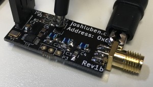
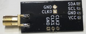
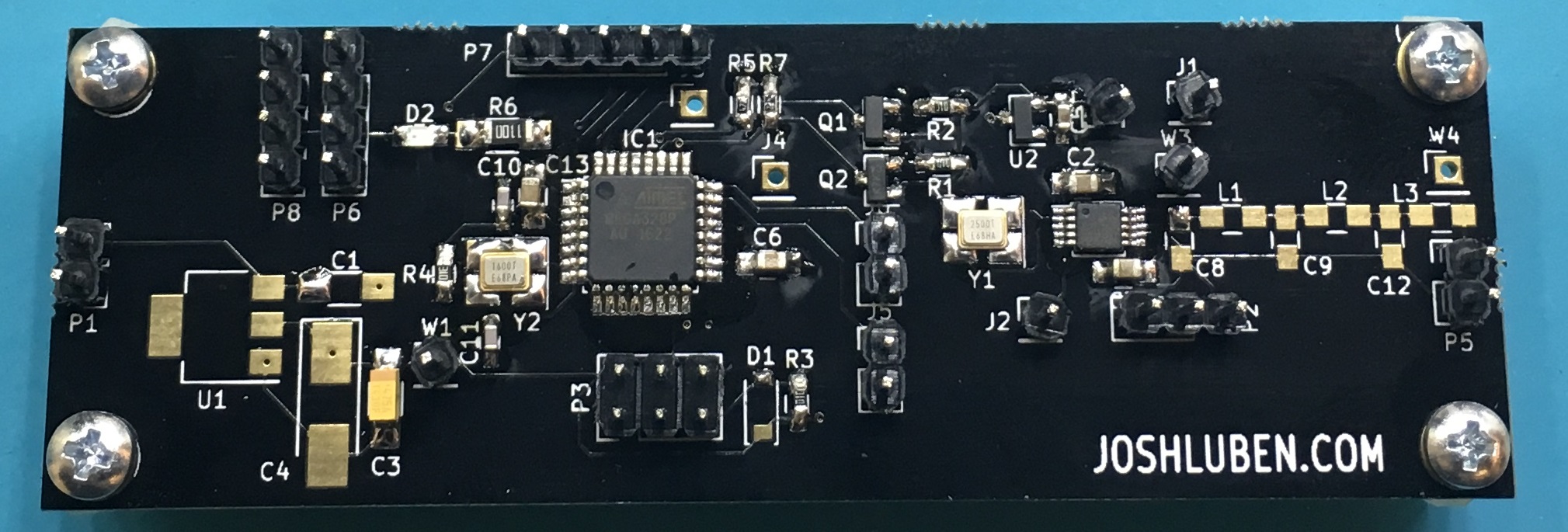
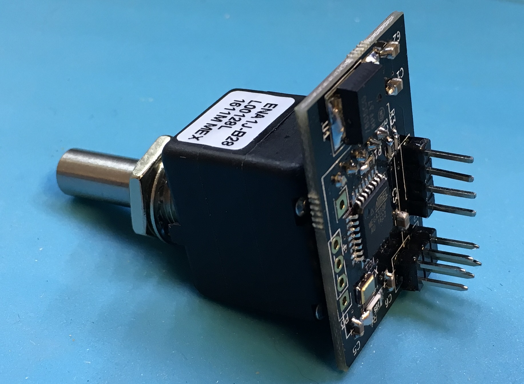
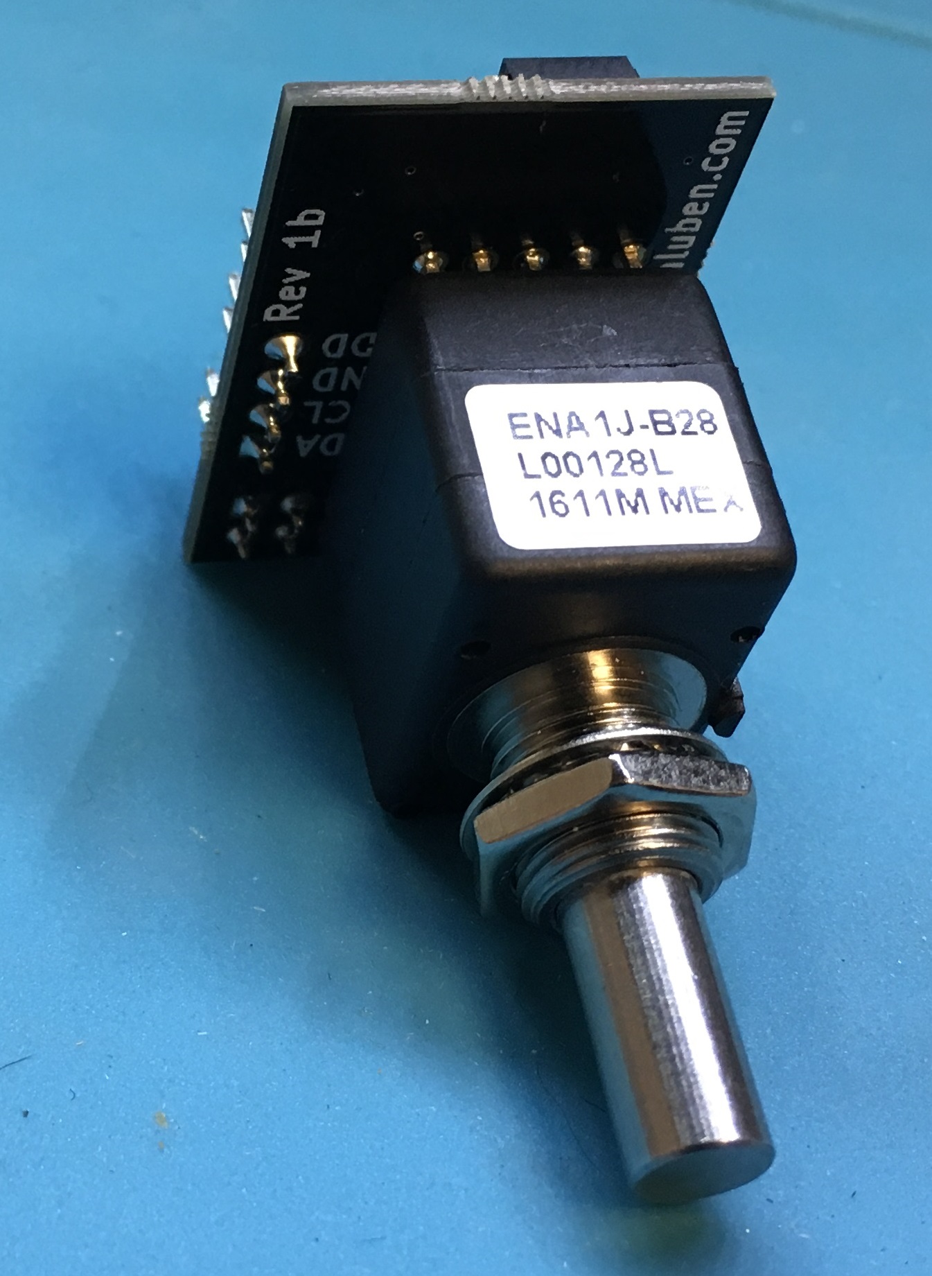
In today’s mail, the latest revision to my Si5351 board arrived from pcbs.io. For me, this board is really a prototype and proof of concept. It is a reusable building block. This module is streamlined I can import it into a larger design in KiCad, remove the headers, and go. The low pass filter is really designed for HF work. One could change the values and reformulate the lpf.
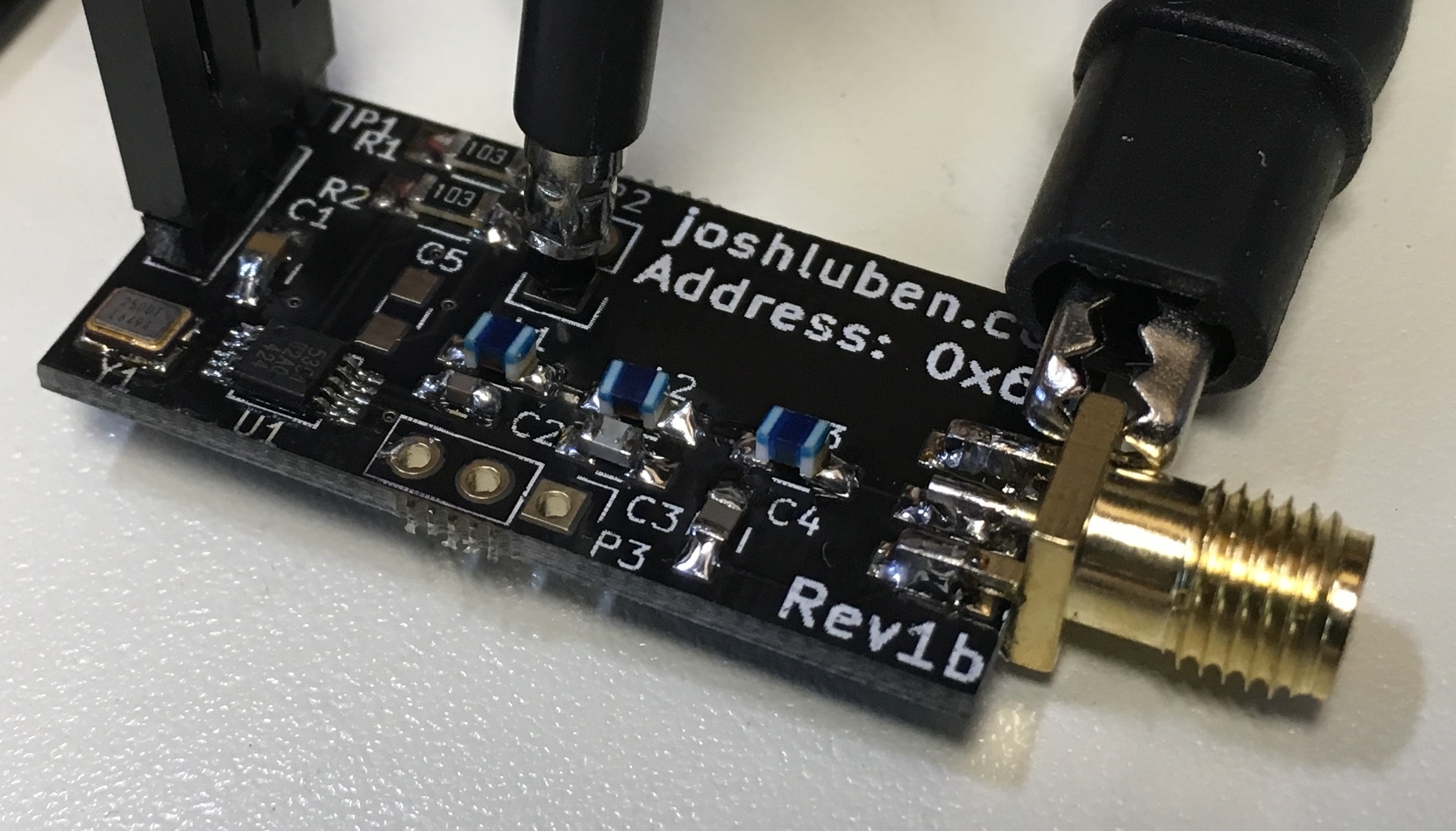
After the kids go to bed, I salvaged the parts from the last generation board and assembled one. It is always thrilling when it works right off the bat. This generation fixes a VCC problem, adds additional bypass capacitors, an extra [optional] header for using outputs two and three. Lastly, lots of markings (documentation on the board).
Build Log: M1 Transceiver: Wiring the Receiver
The last two days I’ve spent laying out the receiver and common IF portions of the M1. I’m basically copying the Minikits suggested layout for the Hammond case. The aluminum sheet divides the inside of the case. The common IF subsystems and receiver modules fit on the top. The DDS and modulator components fit on the bottom. A number of the boards stack.
I purchased a coax crimping tool for RG-316. All the coax jumpers are of my own creation. This cuts down the cost as those jumpers can be quite expensive for quality ones. The SMA jacks and connectors are from China. The jacks rated for a whopping 500 connections! I doubt I’ll hit that ceiling for this project.
Soon, the receiver will be ready for power-on tests and alignment. The front-end mixer has a pad on the LO input, so a Si5351 at the lowest power level will be enough for to play with it.