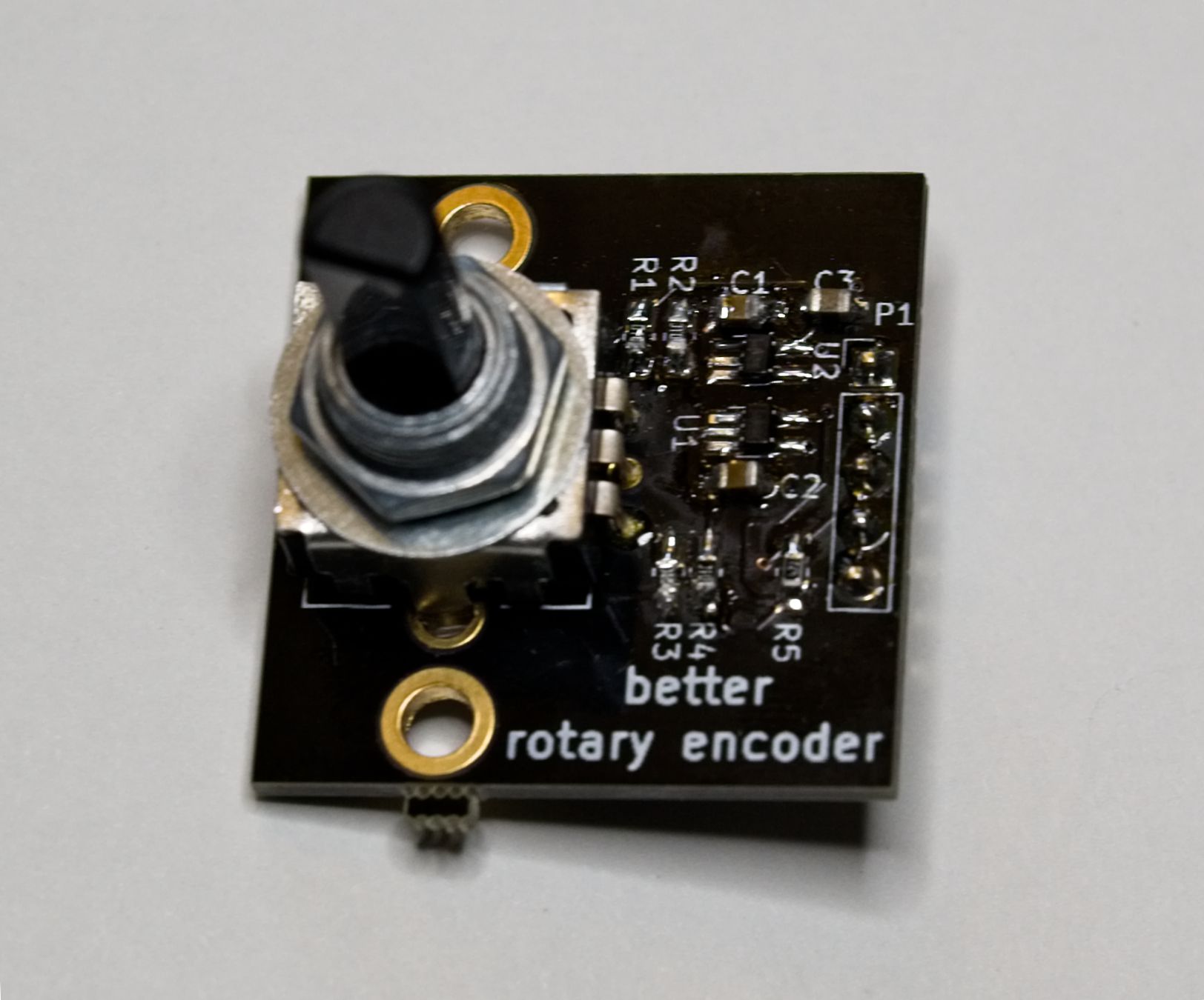
The improved version my rotary encoder breakout board is now available at Tindie. It has Schmitt triggers after the RC debounce for the encoder action. This allows for fast rotary action with minimal jumping.

software creative
The improved version my rotary encoder breakout board is now available at Tindie. It has Schmitt triggers after the RC debounce for the encoder action. This allows for fast rotary action with minimal jumping.
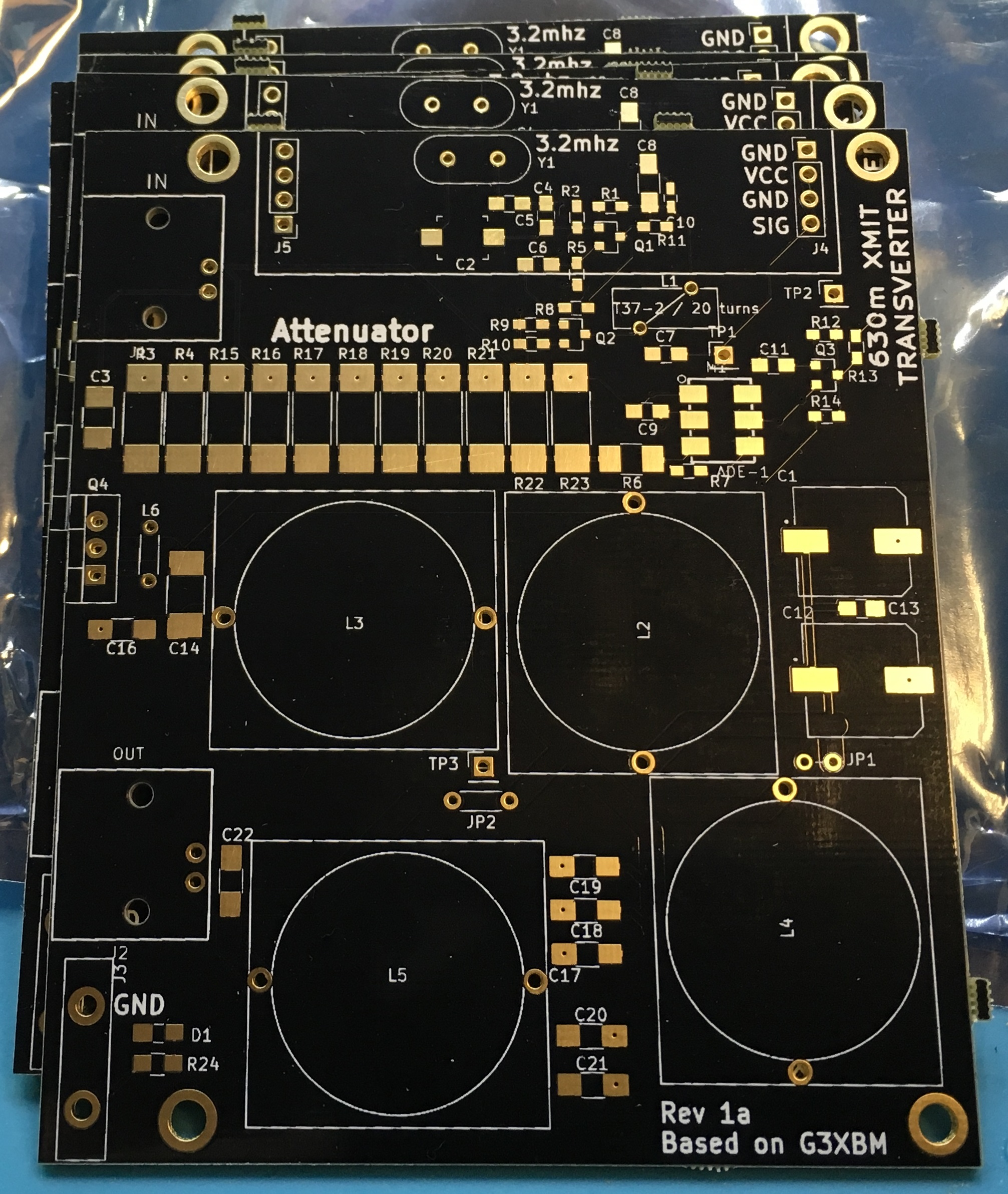
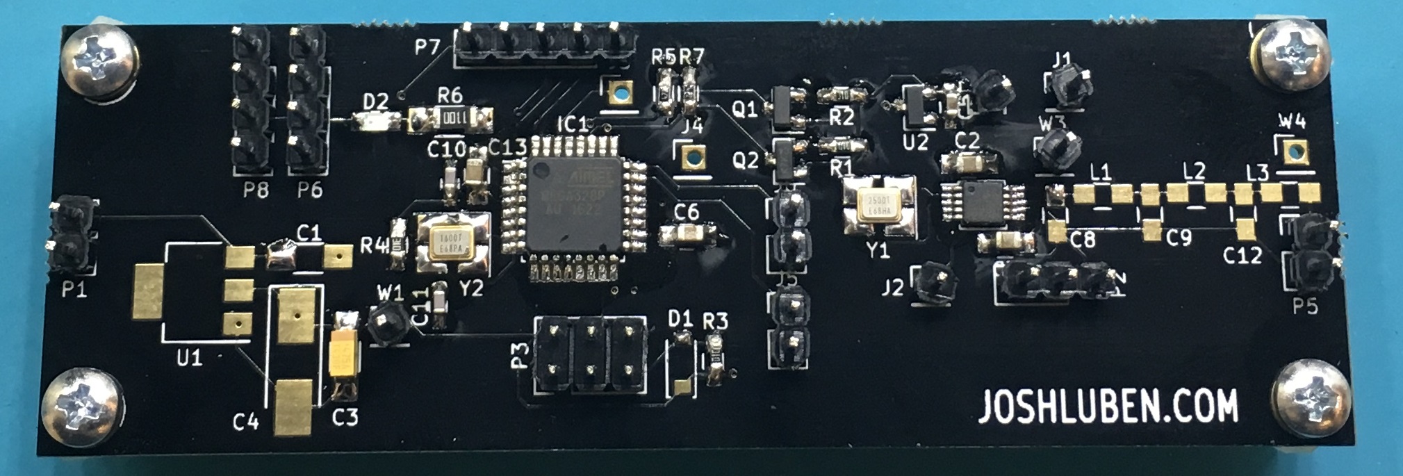
My variation of the G3XBM’s 630m transverter arrived from pcbs.io. This is a surface mount version. Much to my surprise, the surface mount version reduces the parts cost significantly. Also note at the top of board, there are headers to replace the crystal oscillator with a DDS or alternate source.
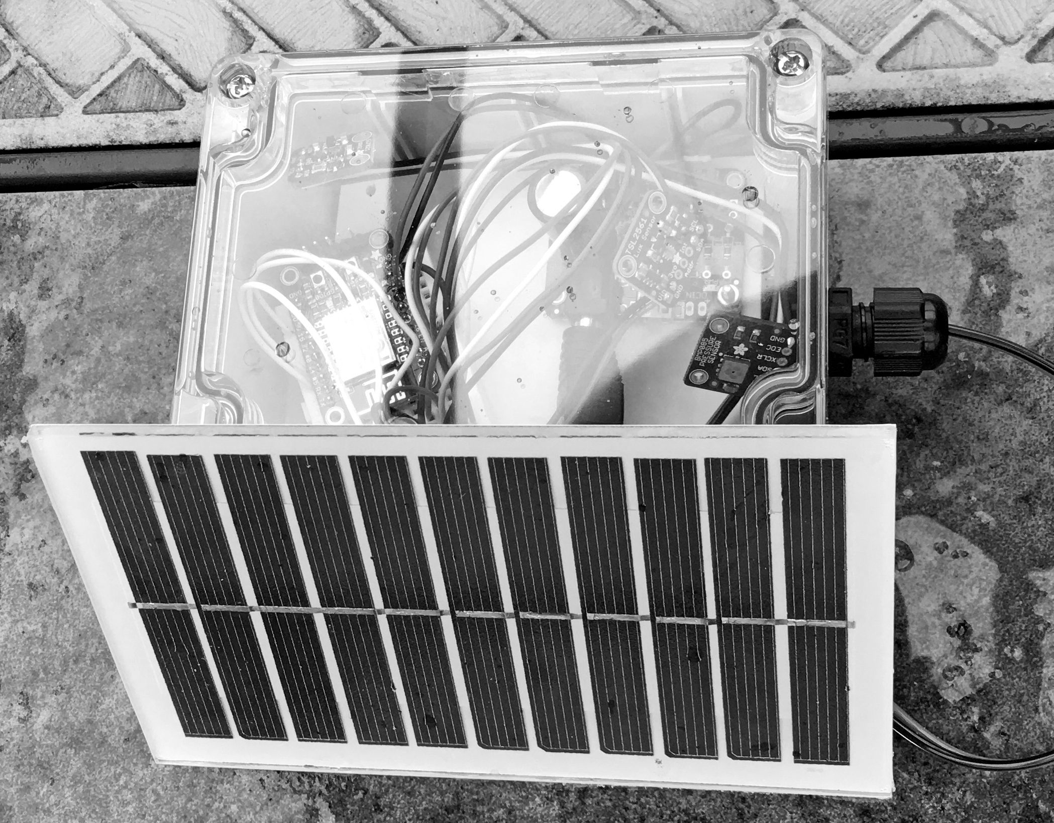
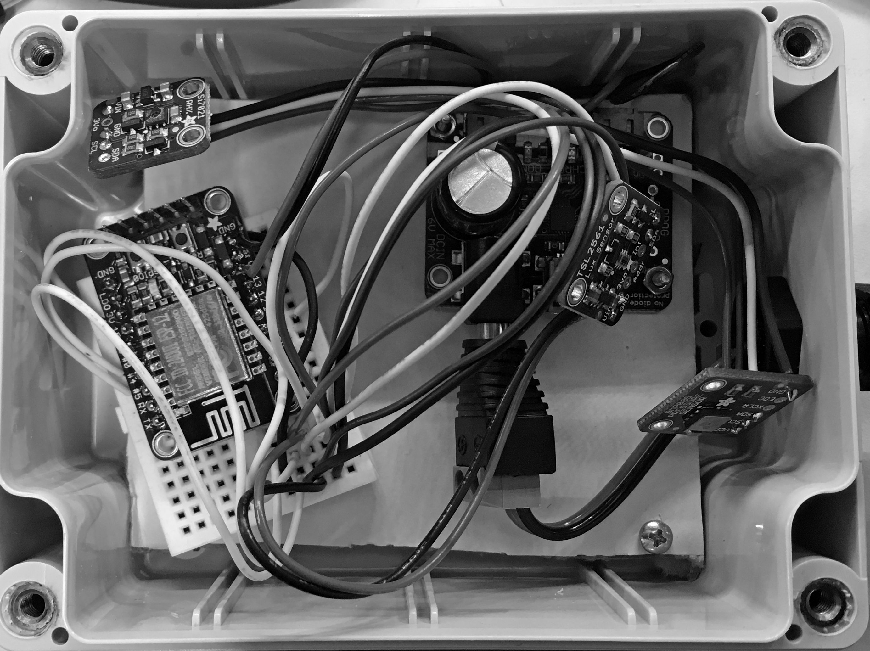
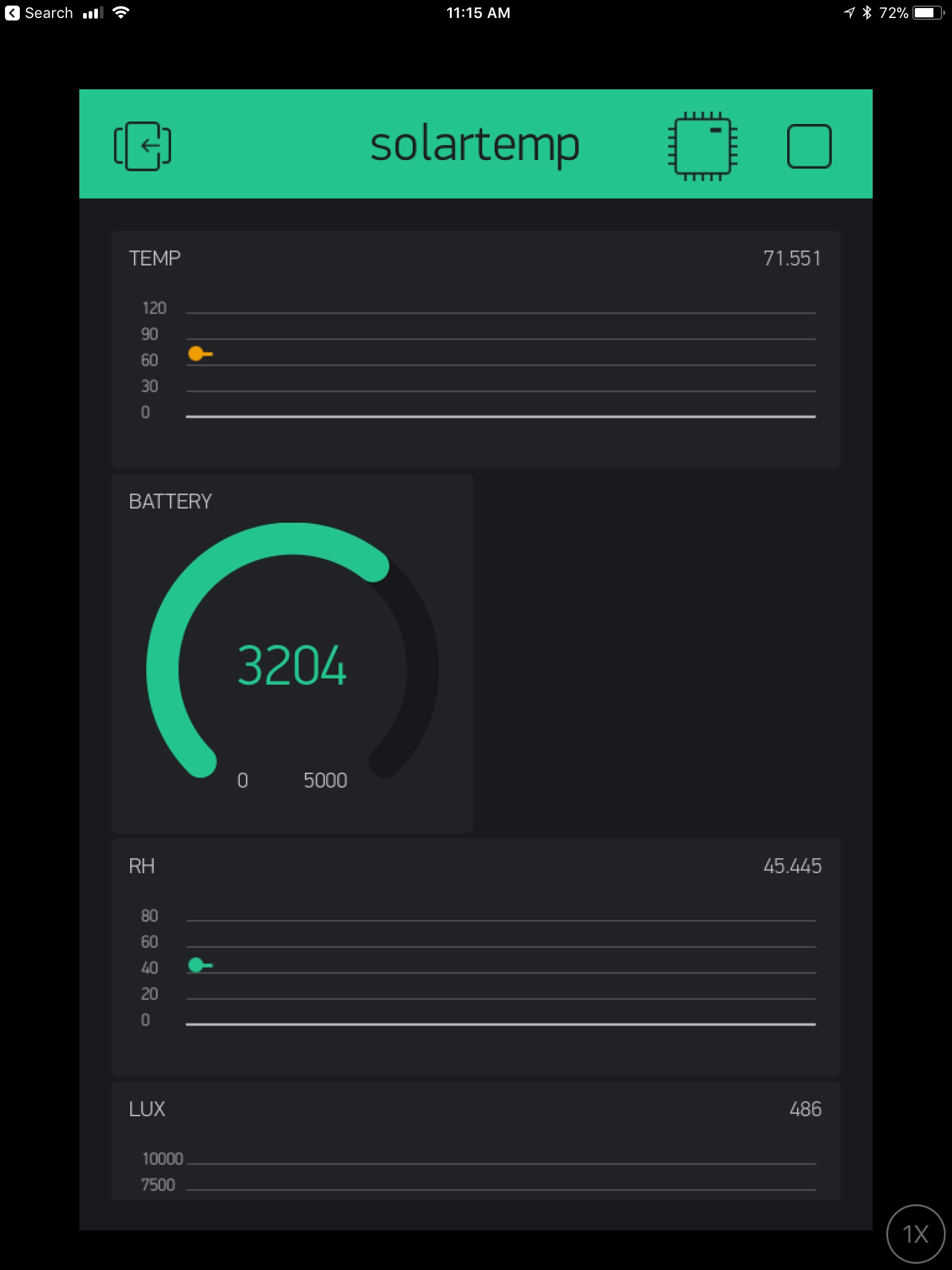
For a while I’ve wanted a system that can report weather data and be solar powered. The ESP8266 is an cheap choice, and this is my first experience using Blynk. The prototype was a weekend project that just needed some assembly. It’s entirely built from Adafruit modules. The EPS8266 is put into deep sleep for 60 seconds…even that may be too frequent. The downside of using the EPS8266 deep sleep mode with Blynk: Blynk often reports the device as offline. I think this is because it can’t do a pull. The EPS8266 wakes up, pushes data, then goes back to sleep.
All the sensors are I2C based. The standard Arduino libraries work right out of the box. If the prototype works well, I might create a pcb that glues everything together.
I’m using the following Adafruit boards:
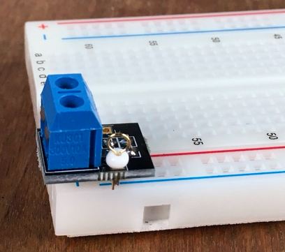
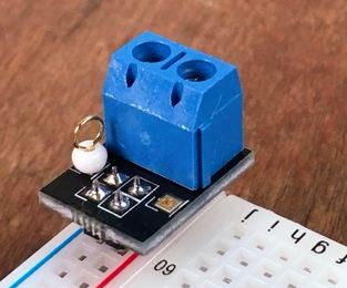
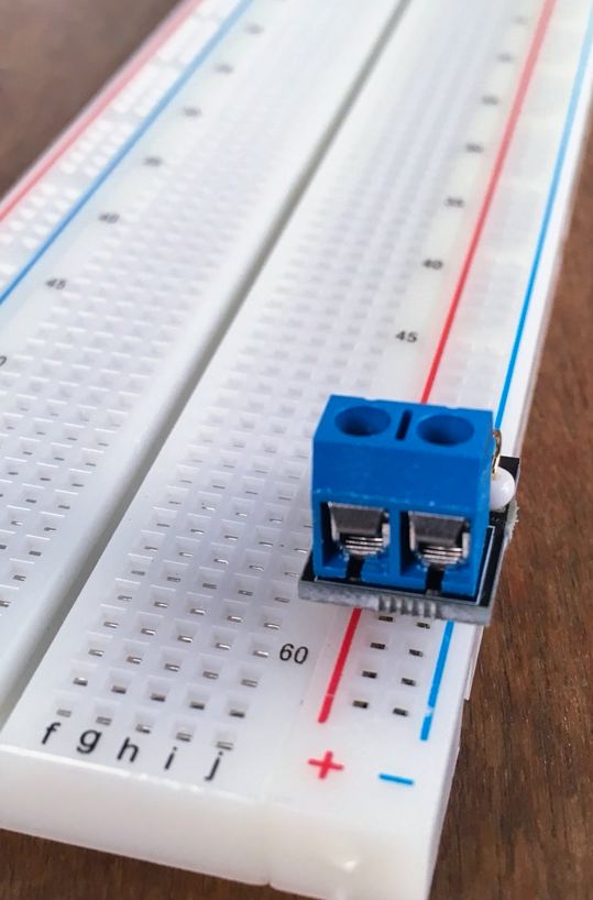
I’ve updated the design of the breadboard helpers. These are designed to sit on the power rails of a breadboard. They provide screw clamps to firmly attach the wire from your power supply or battery. The updated design has a test point that you can attach an alligator clamp (or even scope probe) to.

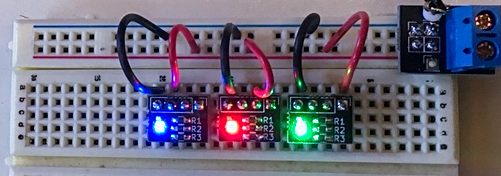
Just another footprint tester. The Everlight 19-337/R6GHBHC is super cheap; but its also pretty small.
You can order this pcb directly from pcbs.io

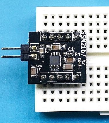
The Analog SSM2167 is “mic conditioner.” I’m most interested in the adjustable compressor. A microphone compressor is a great way to get main gain out of HF radios. The SSM2167 costs less than USD$2 in single unit quantities. It is available in surface mount only packages.
To test this part, I came up with a dip converter for breadboard use. All pins are broken out. If the smd parts are soldered on then the gain is fixed and the compressor is set to 1:4.
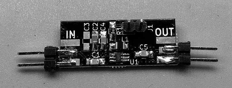
I built a quick breakout board to test the QPA0363ASR at HF frequencies. The spec sheet indicates this part is 0 to 5ghz. Most of these MMIC RF amplifiers are designed to work at higher frequencies and often exclude the 0 to 30mhz HF operating region.
Feeding a -10dbm signal into this breakout board, I was able to get 10db of power gain (as measured with my DPM6000 power meter) with the supply voltage set at 3.8 volts. The spec sheet lists max signal input as -5dbm and max supply voltage as 4.0 volts. I have not optimized the bias resistor or L1 inductor for HF, doing this will probably get a few more decibals of gain.
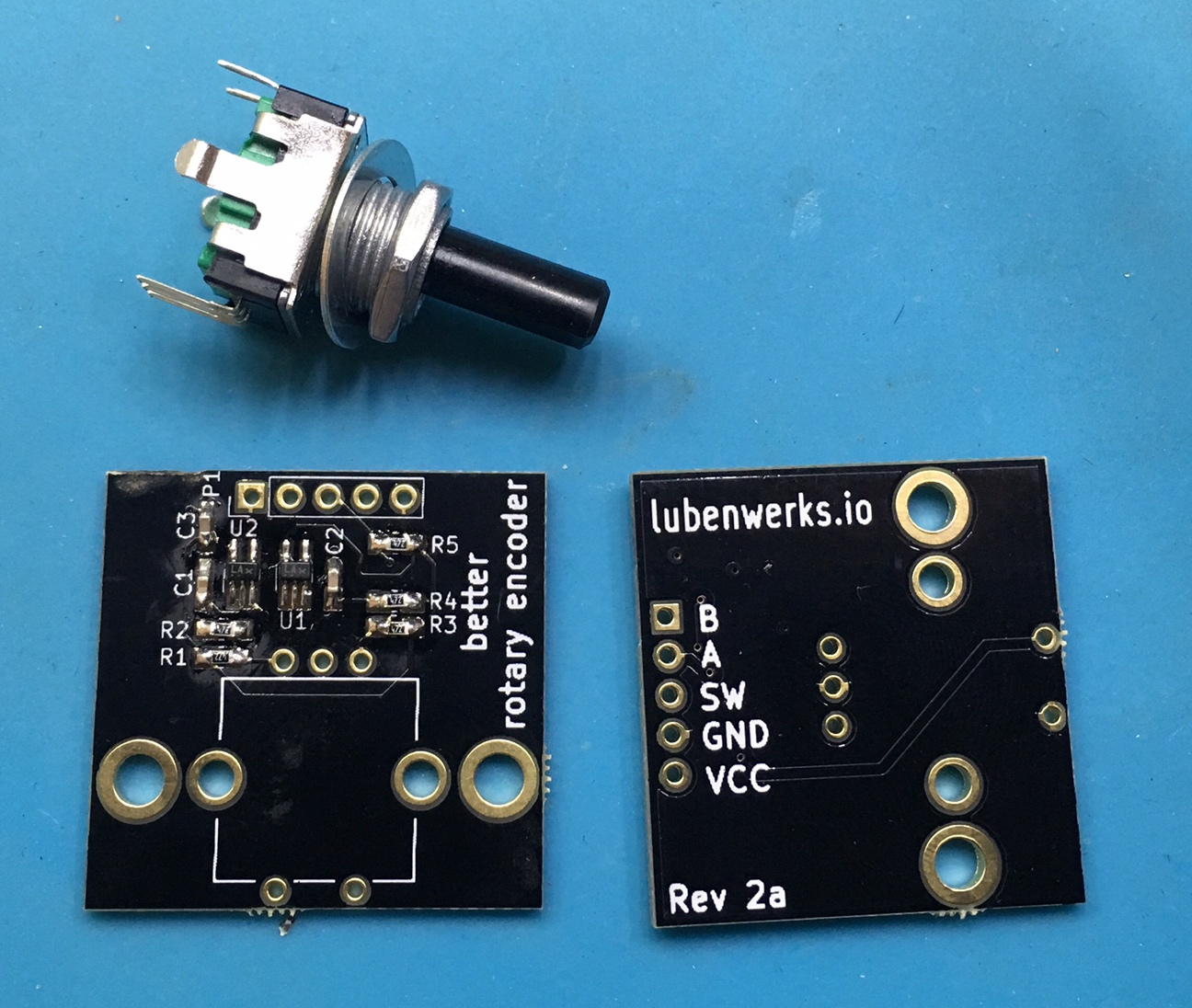
The first manufacturing samples have come back for the “Better” rotary encoder breakout board. This version has two levels of debouncing. The first is the traditional resistor-capacitor network, this is fed into individual schmitt trigger inverters. The output waveforms are nice enough to use on an Arduino without interrupts.
You can buy the Original Mountable Rotary Encoder Board on Tindie. The “Better” version is going out to some beta-testers before I put it up for sale.
It’s been a pretty busy summer so far. The primary project on the BITX40. I decided to build my own DDS board for it. It’s based on an Atmel 328p, and has headers for the I2C OLED display, rotary encoder, and some extras. This board uses a Si5351A and has a five pole low pass filter on the output. This low pass filter nicely shapes the waveform into a Sine wave. There are some additional inputs if I want to add temperature, power, or SWR sensors.
As of this evening, I have the display, rotary encoder, and DDS output working together. More pictures to come. I have several of these boards that are spare. I’ll probably put the spares on my Tindie store.
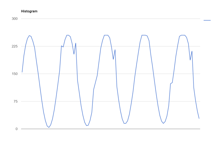
I’m working up a Raspberry PI 3 add-on that gives the user a single 8 bit A/D channel. Over the last week I tried pushing this $2 adc chip as fast as possible via bit banging (no SPI here). Others have reported that they can toggle a GPIO pin fast enough to generate a clock in the high 20mhz range.
20khz at 600mv P-P
50khz
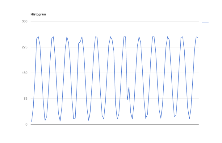
100khz
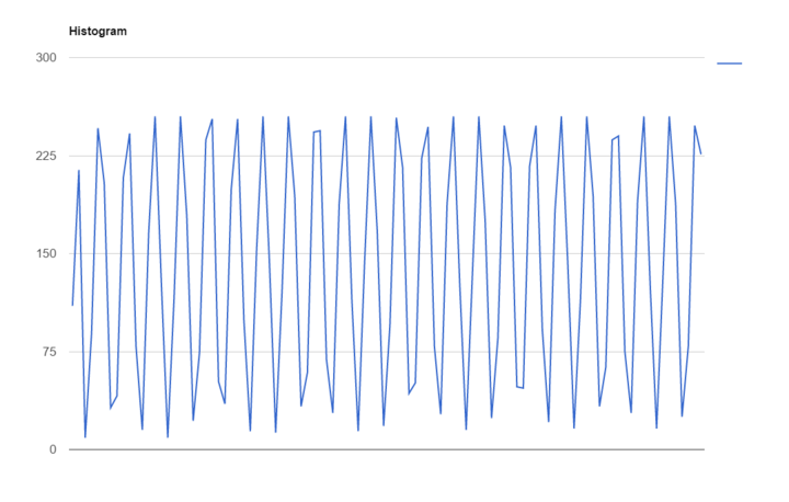
Here at 200khz you can see that data is starting to get lost
// The following code uses macros from http://elinux.org/RPi_GPIO_Code_Samples

for (samples=0 ; samples < kSampleCount ; ++samples)

{

GPIO_CLR = 1<<CS;
value = 0;
for (i=0 ; i < 16 ; ++i)
{
GPIO_SET = 1<<SCLK;
GPIO_CLR = 1<<SCLK;
if (i > 0 && i < 9)
{
bit = GET_GPIO(DIN) > 0 ? 1 : 0;
if (bit)
value |= 1 << (i-1);
}
}
GPIO_SET = 1<<CS;
sampleData[samples] = reverse(value); // Convert from MSB to LSB
}