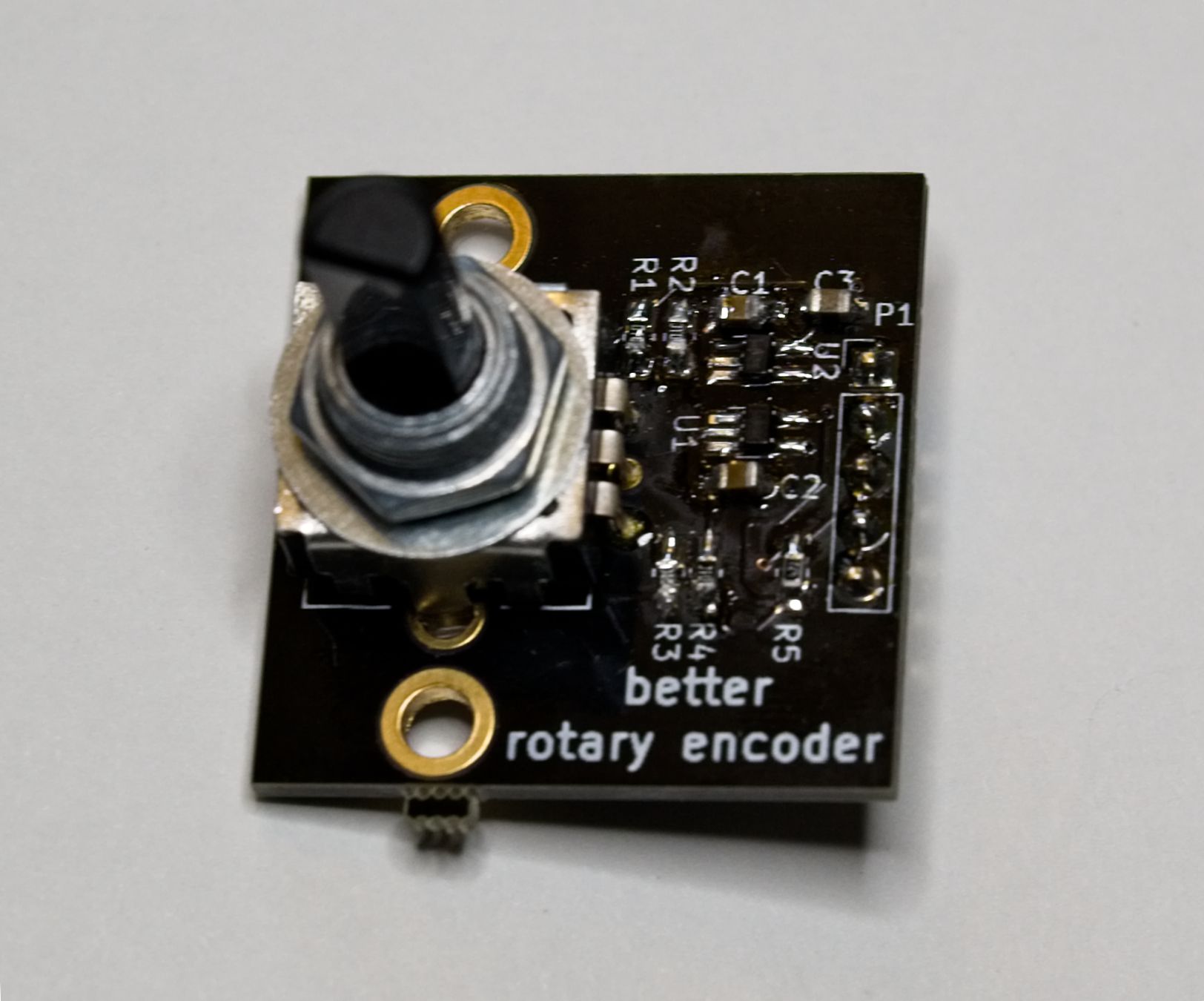
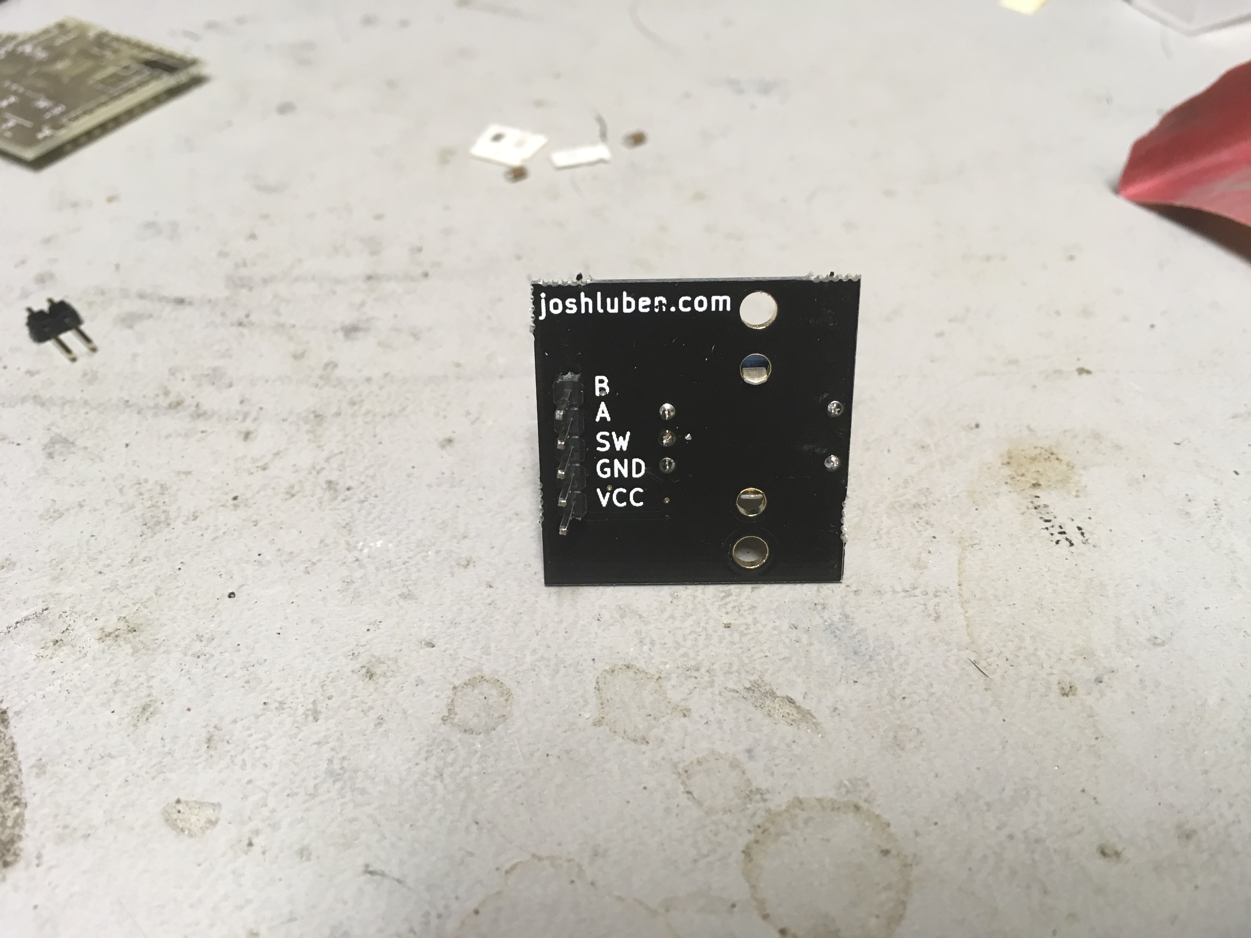
The improved version my rotary encoder breakout board is now available at Tindie. It has Schmitt triggers after the RC debounce for the encoder action. This allows for fast rotary action with minimal jumping.

software creative
The improved version my rotary encoder breakout board is now available at Tindie. It has Schmitt triggers after the RC debounce for the encoder action. This allows for fast rotary action with minimal jumping.
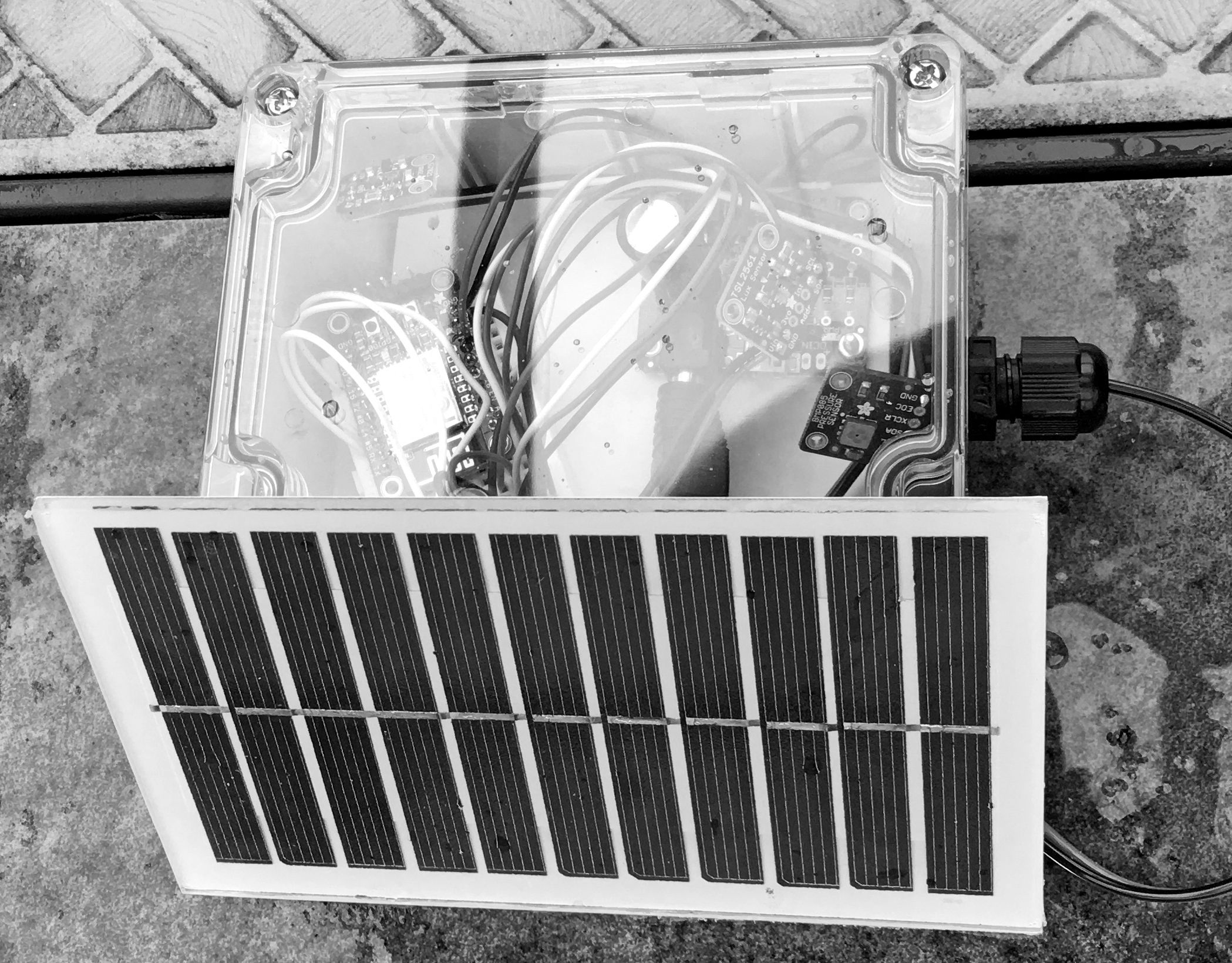
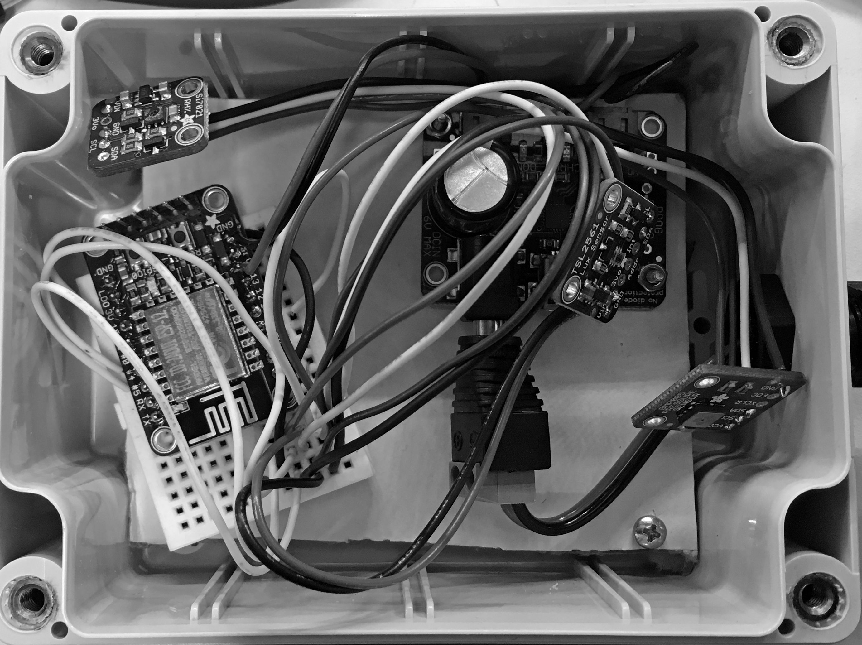
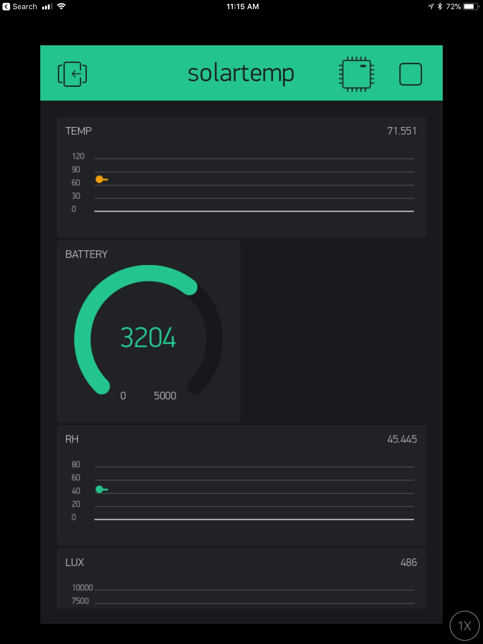
For a while I’ve wanted a system that can report weather data and be solar powered. The ESP8266 is an cheap choice, and this is my first experience using Blynk. The prototype was a weekend project that just needed some assembly. It’s entirely built from Adafruit modules. The EPS8266 is put into deep sleep for 60 seconds…even that may be too frequent. The downside of using the EPS8266 deep sleep mode with Blynk: Blynk often reports the device as offline. I think this is because it can’t do a pull. The EPS8266 wakes up, pushes data, then goes back to sleep.
All the sensors are I2C based. The standard Arduino libraries work right out of the box. If the prototype works well, I might create a pcb that glues everything together.
I’m using the following Adafruit boards:
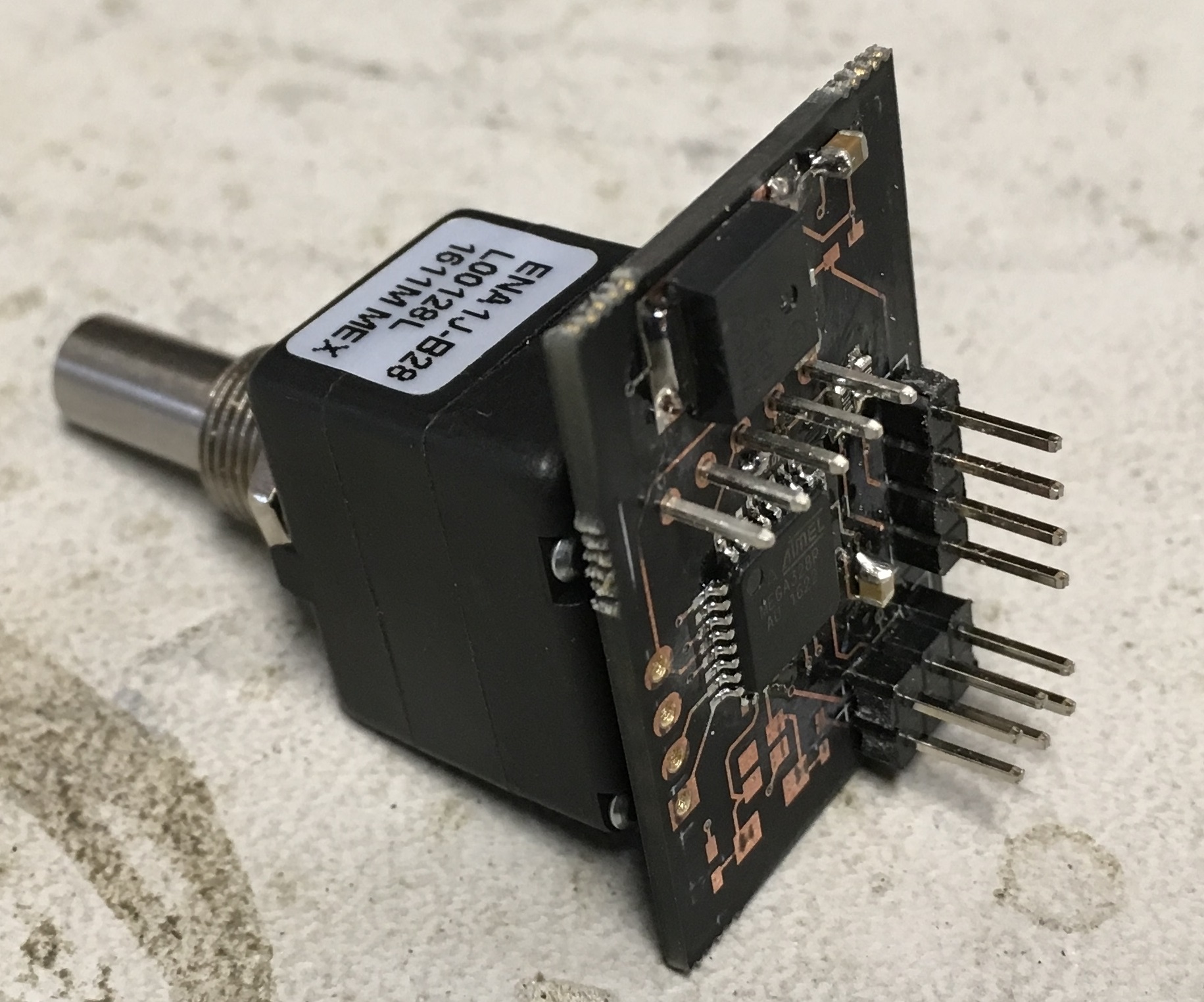
I purchased a Bourns ENA1J serial rotary optical encoder. This control has a nicely weighted shaft that uses ball bearings. It is rated for >= 10 million rotations. The ENA1J outputs beautiful square signals (unlike mechanical rotary encoders). I think I paid USD$35 for this premium part. You will find optical rotary encoders on high end radios like the Elecraft K3 and professional mixer boards.
I designed a pcb that takes the quadrature output of the ENA1J into INT0 and INT1 inputs of the ATMEGA328P mcu. A pin header gives access to the I2C bus that allows this to be used as a satellite peripheral.
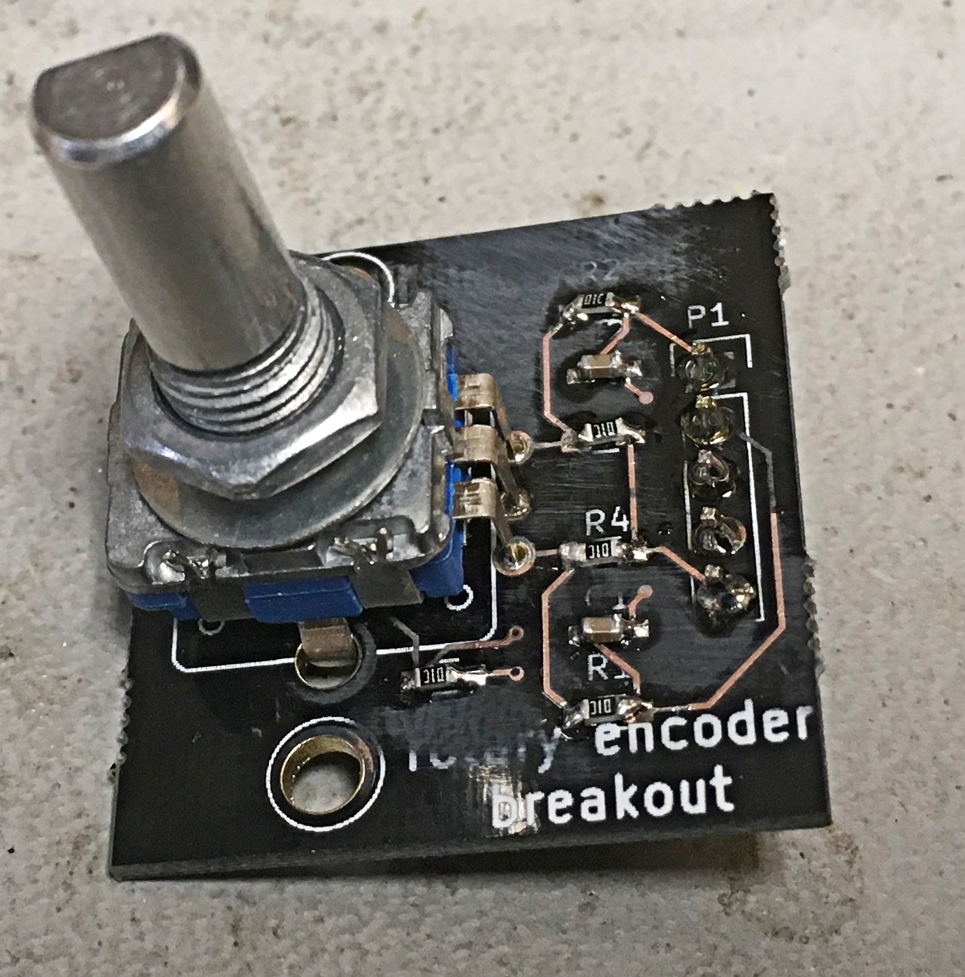
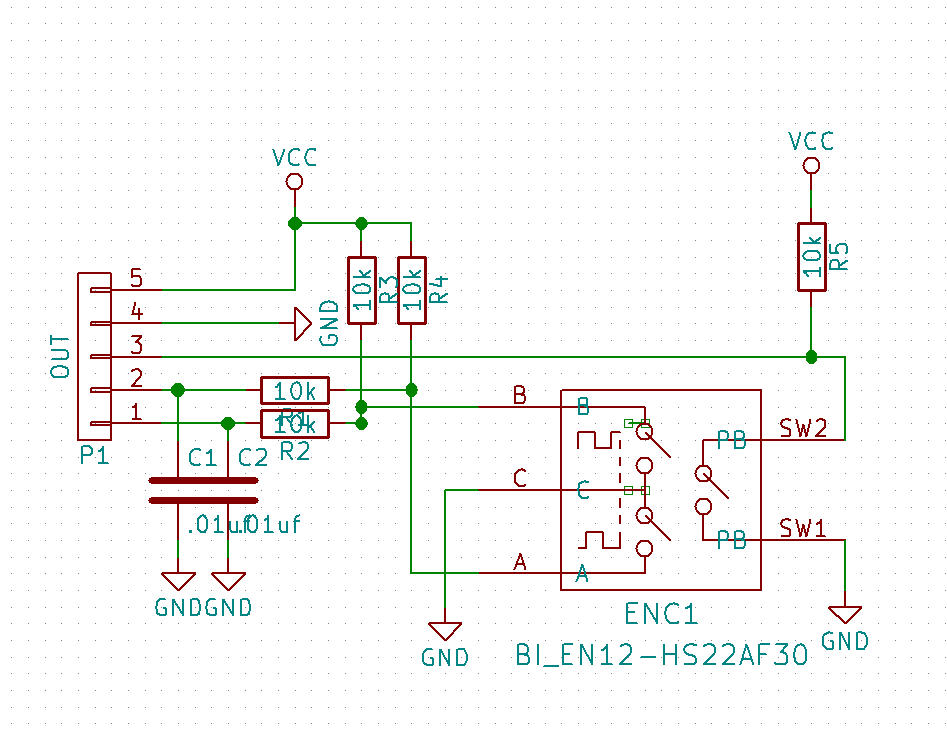
I created this breakout board that enables easy use and mounting of a mechanical rotary encoder. This kind of rotary encoder suffers from debounce problems. The easiest way to address it is to put a RC network on each leg of the rotary switch. This board has mounting holes in case one ends up using encoders that do not have threads.
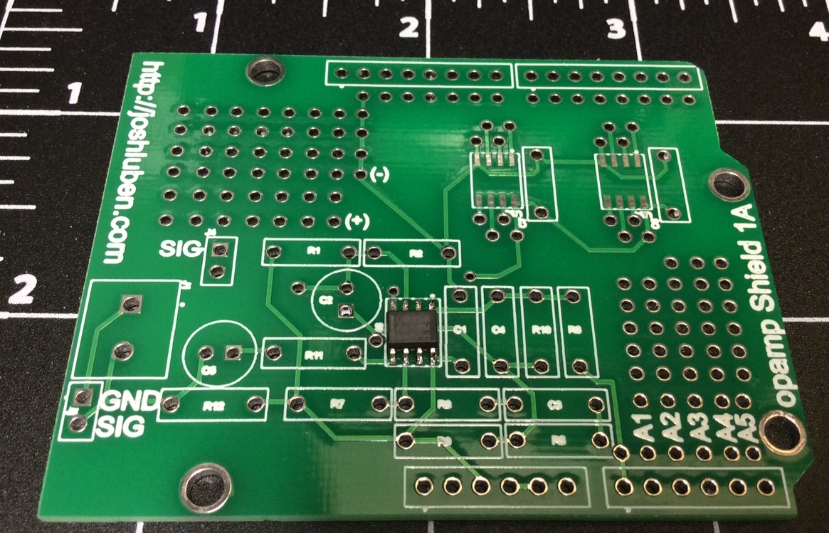
Recently I needed an op-amp front end for taking some measurements using a bpw34. I put together a circuit on a bread board, took the measurements, then put all the parts back. I decided to build a shield that can be configured for two or three different op-amp configurations, then feed the signal into A0. The core circuit uses a LM358D with a soic footprint. All other parts are thru hole. There is some prototype space, and two additional soic-8 footprints.
The LM358 has two op-amps in it. They are chained together, One could bypass the first or second stage by soldering a jumper.The second stage has a voltage divider that brings the input voltage to Vcc/2. The second stage also provides some feedback (if you solder in R6 and C4). This and a few other changes provide about six permutations of highly useful op-amp circuits.
My first draft has a few minor errors, but is usable. The next step is to write a comprehensive manual that lays out multiple use cases.
I’ve been thinking about how to teach my kids quantifiable science. I got a cheap science kit off Amazon for the kids a while back. The kit uses color changes to measure reactions using plant-based powders, but this is a binary outcome. It works or doesn’t. This is great for the first one or two experiments, but doesn’t really teach enduring principles, such as taking measurements, graphing, and ultimately forming to a conclusion.
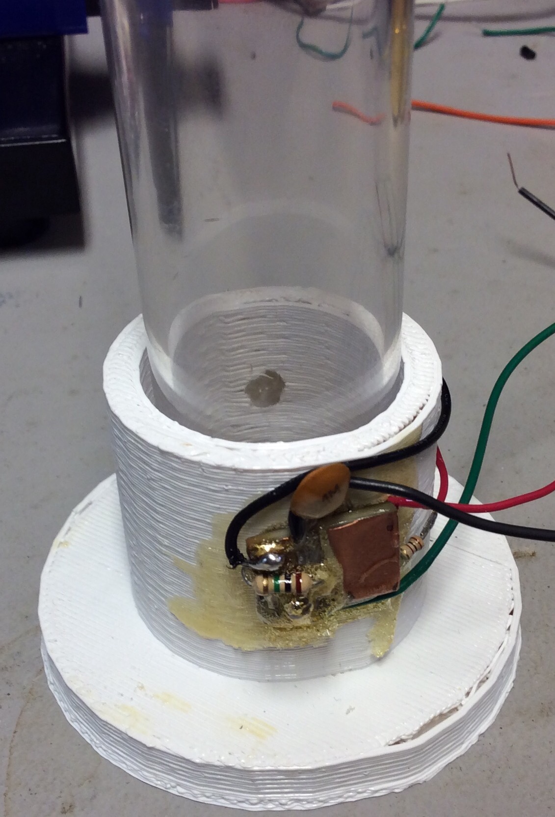
The general idea behind measuring absorbance is to shine a light through a corvette (or test tube) and measure the amount of light that makes it through. Fancier instruments will use multiple wavelengths or an entire spectrum.
To keep this simple, I used a 3D printer to fabricate a holder for the test tubes from the science kit. A 635nm red LED shines in one side, and a BPW35 detects the light. The next step is to mount this on a small plastic project box with a cheap two line LCD display. A button (or two) will control taking measurements (and some kind of integrated calibration cycle).
This instrument will enable a simple number to be presented to the user. My kids can then perform reactions or dilute samples, and graph those numbers (math yeah).

Installing a custom/dedicated web server on the Arduino Yun is a little tedious. Instead, one can reuse the already running uhttpd instance that is used for luci. uhttpd was written specifically for openwrt. Configuring it is pretty easy. The Yun image (and most of openwrt) configures uhttp by command line switches.
/usr/sbin/uhttpd -f -h /www -r Arduino -x /cgi-bin -t 60 -T 30 -A 1 -n 2 -p 0.0.0.0:80 -C /etc/uhttpd.crt -K /etc/uhttpd.key -s 0.0.0.0:443
The content directory is at /www and only scripts in /www/cgi-bin are allowed to execute. To test this, you can put a python script at /www/cgi-bin/test.py
#!/usr/bin/python
import cgi
print(“Content-type: text/html\n”);
print(“Hello World”);
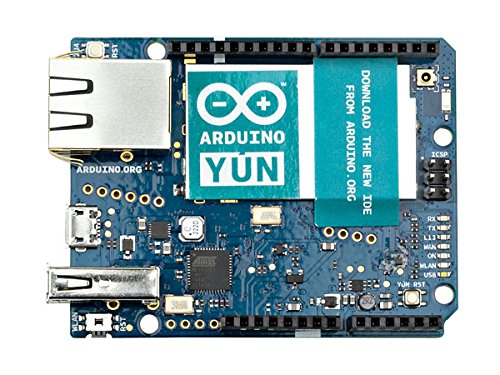
The Yun has a bridge mechanism that allows the two processors to communicate. This is documented here. To hook up these two mechanisms, you need to download the tutorial sketch and put it on the Yun. The basic idea is that you can execute HTTP GET commands against a series of simple “Bridge” REST services that get and set the pins on the Arduino YUN.
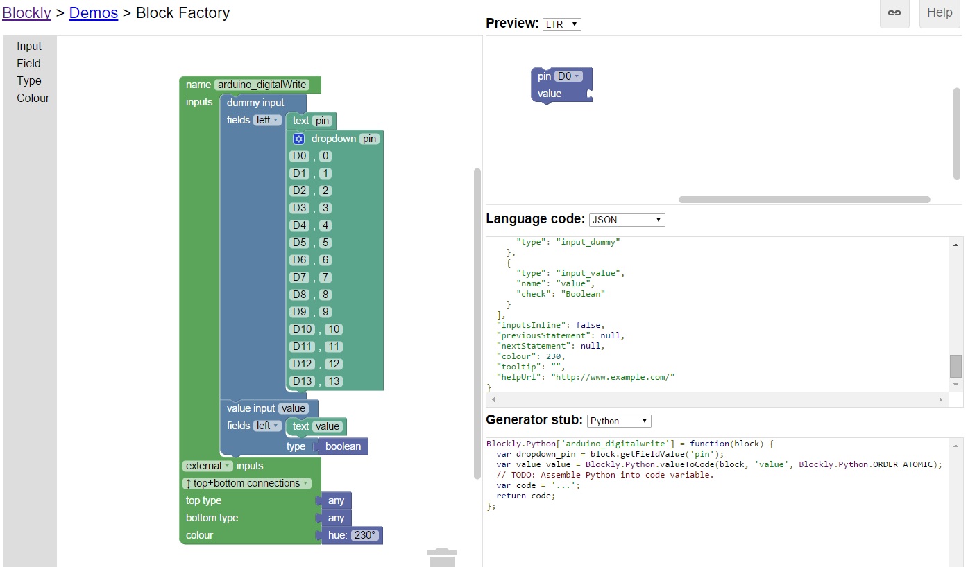
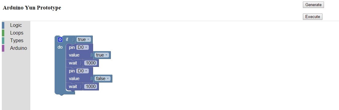
What fun is a simple web page with some buttons when you can use Google Blockly? The Yun does not have much storage space. I had to install Blockly and other files on a micro SD card. I prototyped just enough custom blocks to blink a light. I only need two custom blocks: wait and writeDigital.
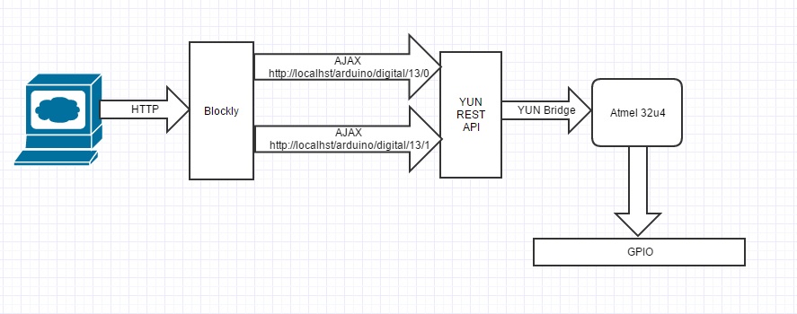
The process flow looks like this. Because the JavaScript code that each Blockly block runs locally, then can send AJAX requests back to the YUN’s web server. Each AJAX request can then use the YUN bridge to modify the GPIO.
The actual Blockly program looks like this:
Maxim makes this small ADC that comes in SOT23 and other packages. The cost runs from $1.65 to a few dollars depending on if you choose 8, 10, or 12 bit variants. They boast sample rates up to 2 or 3 mega samples per second. These are 3V only chips. They are not 5V tolerant. This should make it easy to use with ARM or Raspberry PI boards.
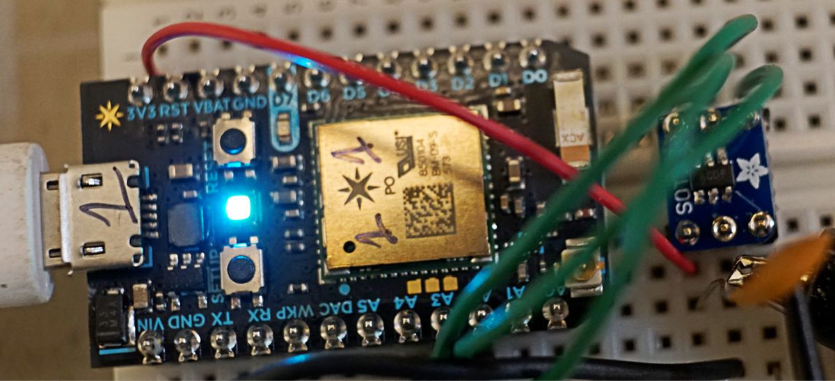
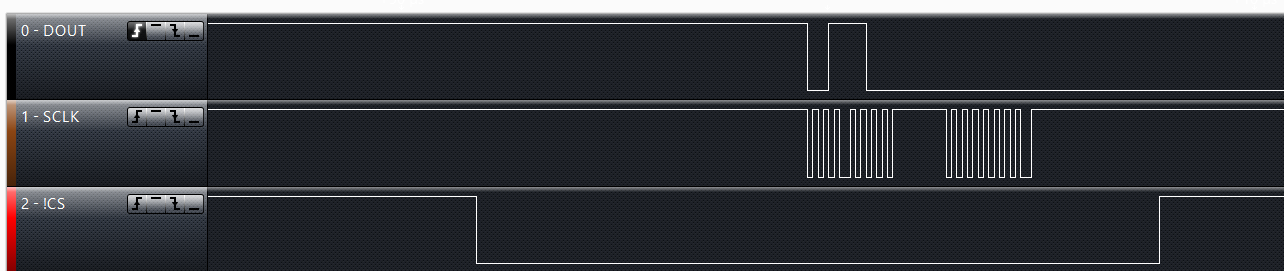
I wanted to verify this work and get some proof of concept code. I chose to use the MAX11115AUT+T that I soldered onto an Adafruit SOT23 breakout board. The ADC can communicate use several digital protocols including SPI. It only takes three wires to control it: SCLK, MISO, and !CS. When CS goes low, the SPI clock drives the digitizing of the signal. After one clock, the first bit is available on DOUT. An new bit is available each clock pulse. The ADC always writes two bytes out. If you are using the 8 bit ADC, you still need to read in the second byte.
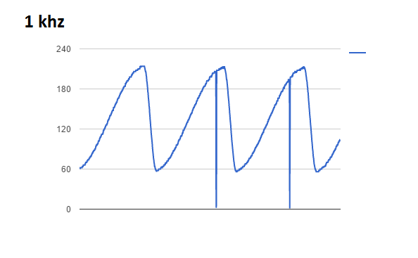
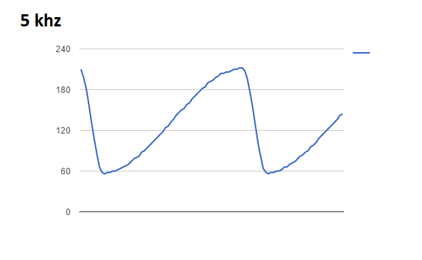
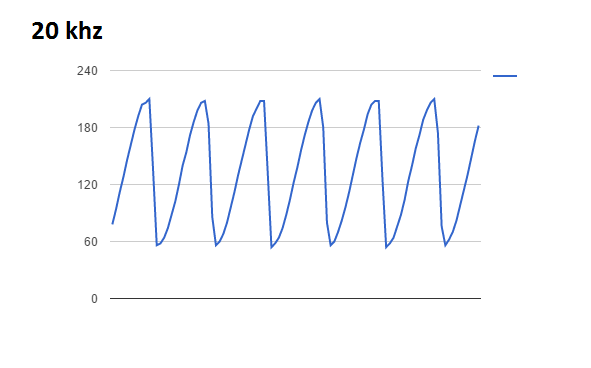
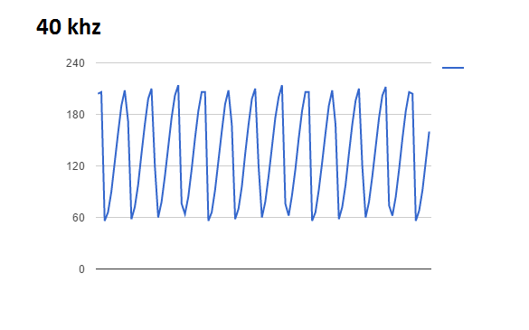
To test the sample rate, I wrote some code on the Particle Photon that reads in 100 samples, stores it in a buffer, then transmits it over TCP to a local python server. A signal generator is feeding the ADC a sine wave. Here is what the raw data looks like at various input rates. Please keep in mind this is a quick proof of concept. There is no buffering, impedance matching, or anti-aliasing. The SPI bus is running at Photon’s default clock speed.
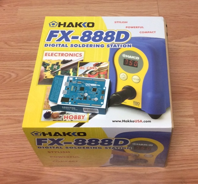
My birthday came and went. My wonderful wife got me a Hakko FX-888D. My dad got me an Arduino Zero Pro. Sweet!
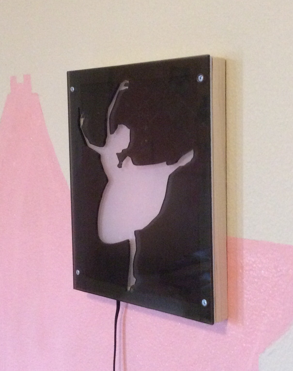
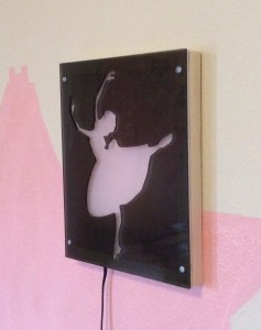
Luci, my middle daughter wanted a new nightlight because her store-special fairy one broke. We came up with the idea of a ballet night light.
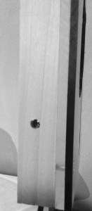
I took some scrap acrylic from Tap Plastic’s remnants bin, cut them square on the table saw, then traced the silhouette of a ballerina on the opaque sheet. The opaque sheet sits on top of the transparent sheet. The acrylic is screwed on a small poplar frame. I put a white sheet of vellum on the inside of the acrylic to diffuse the light from the LED’s.
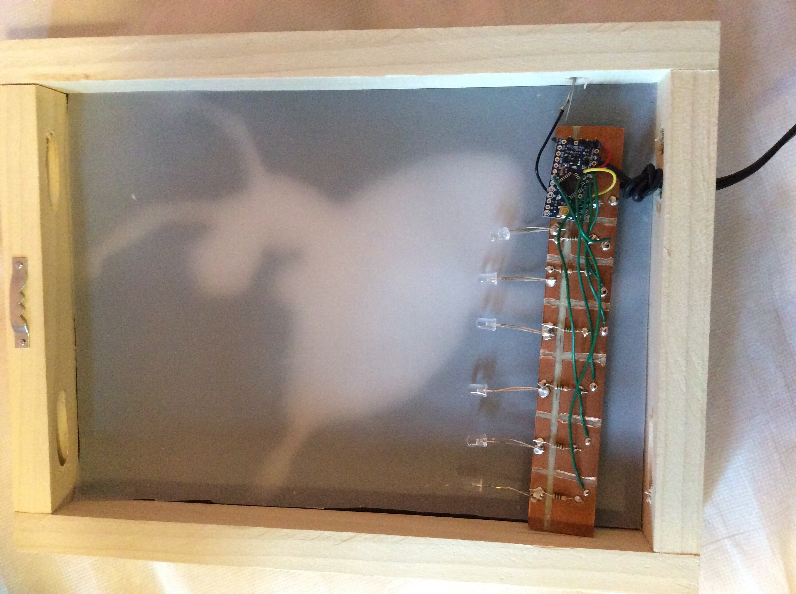
Several LED’s a soldered on a [very] crudely fashioned bus made of copper PCB. An Arduino Mini drives the LED’s on the PWM digital ports, and reads the ambient light. The night light only comes on when it is dark. Each LED is on a separate digital output. I wrote a simple flashy sequence into the unit when the unit comes on. Turns out Luci does not like the flashy lights. She just wants it to turn on at night and off during the day.