Bare bones assembly instructions for LM380 audio amp

There is a minimal number of parts necessary to enable the audio amp on this PCB.

  1. Install U2, the LM380
  2. Install electrolytic capacitor C3. I used a 100uF here. You can use a bigger/smaller value if you want (changes) the frequency response.
  3. Install resistor R1. This can be anywhere between 2.2 and 30 ohms. This resistor should be rated for at least a half watt.
  4. Install filtering capacitors C1 and C2.
  5. If you want on board volume control, install potentiometer R15. The footprint is for a Bourns PTV09A-4020F-A103 available at Mouser for $0.70. If you use R15, then jumper pins 1 and 3 of J3.
  6. You can use an external potentiometer by using header J3 and pins 1 (GND), 3 (U2 input), and 4 (SIG). Feed the audio input into pin 3 of J1.
  7. The board has four mounting holes for 4-40 screws. There should be enough space to use R15 and mount the hold board against a panel if the headers are solder on the back of the board.

LM380 pcb

20m RF Amp, Ugly Style

Today’s Saturday project was to solder up ugly style a 20m RF amplifier that resided on my bench for like six months. It’s been nearly a decade since I did anything ugly or Manhattan style. This project was actually an excuse to design a RF low pass filter and test it with my Rigol spectrum analyzer. The screen shots below show that the first harmonic is suppressed by 26db. Mysteriously, there is a harmonic below the primary frequency. I used a 2N3866 power transistor. This are getting hard to find, but I’ve managed to get a supply from Aliexpress.

_KD7QJL 20m RF AMP

1

2

Edit 2014-12-25:

I used the low pass filter to test the miniVNA Pro. Here is what the loss response looks like:

20m ugly amp loss response

Cheap webcams on raspberry pi and HTTP

I finally found a webcam and software combination that is not only cheap, but relatively easy to setup. Being a cheapskate, I have avoided the Raspberry pi camera. The Raspberry pi camera has several things going for it (from what I gather): lower power consumption, faster response, and it does not use a USB port. I ordered a very cheap webcam (rather blindly) from Amazon hoping it will work. lsusb indicates it is made by Aveo (or at least compatible) and comes up with ID 1871:0101 (my kernel is 3.10.25). This webcam works without a powered USB hub. It typically shows up in the device tree as /dev/video0 (if it’s the only device you have plugged in). I’ve found that the rpi does not supply enough USB power to power the camera and anything else (including a keyboard).

Edit: Demo images
test7

5MP webcam test images

test3

test6
(Amazon Link)

There are several different software packages out there:

  • raspistill for the Official Rasperry pi camera
  • OpenCV or SimpleCV
  • pygame
  • imgproc a library for Python (no save capability)
  • fswebcam

I’ve found fswebcam to be the fastest way of getting started. I burned a lot of time looking at OpenCV or combinations of mpeg-streamer. fswebcam just works. It comes in a package:

sudo apt-get install fswebcam

and it is very easy to use:

fswebcam -d /dev/video0 -r 640x480 test.jpg

and it is very easy to use:

fswebcam -d /dev/video0 -r 640x480 test.jpg

I found that the software can sometimes return an image that contains parts of two frames, like this:
messedup

To avoid this problem, tell the program to skip two frames:

fswebcam -d /dev/video0 -S 2 -r 640x480 test.jpg

There is also a background mode (using -b) to enable it run as a background daemon. So far fswebcam will not retrieve images at greater than 640×480 resolution from this camera.

Raspberry webcam

Flying PigRig #316

Finished up the transceiver and ran it through the alignment process. My frequency counter nor my signal generator are accurate to enough decimal places. I ended up aligning it by ear. The oscillator output is a nice clean sign wave. The output looks excellent after a quick look at the output on spectrum analyzer.

Mounted in a case. The included copper heat sink appears to be quite adequate. Still having thoughts about what type of power cable to use. My preference is Anderson PowerPole, but there are not a lot of chassis mounting options. I’m considering ordering some Anderson AutoGrip blocks from Hardened Power Systems.

20131226-211106.jpg

20131228-160001.jpg

20131228-162410.jpg

Building a TRAC bug display using Digispark

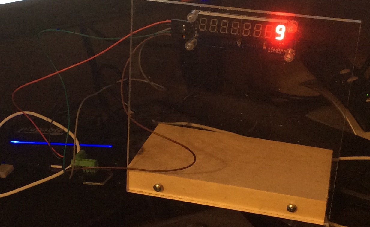
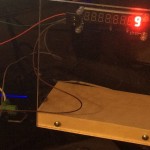
I decided to build a display for my desk at work that shows my current bug count using the 7 digit segment display that I purchased from DealExtreme. I do not want an Arduino hanging off a USB cable cluttering my desk (or draining my wallet). Enter the Digispark. Designed and produced by a local Portland company, the Digispark is an ATtiny85 that fits directly into a USB port.

On the computer side, A python program runs on my desktop. It queries Trac every once in a while and if the bug count changes, sends a message to the display.

IMG_0069

Code for the Digispark:

#include <DigiUSB.h>

#define latch 0
#define clock 1
#define data 2
#define kDigitCount 8

char gDisplayBuffer[kDigitCount+1];

void setup()
{
   pinMode(latch, OUTPUT);
   pinMode(clock, OUTPUT);
   pinMode(data, OUTPUT);
   
   memset(gDisplayBuffer, ' ', kDigitCount);
   writeToDisplay(true);
   
   DigiUSB.begin(); // open DigiUSB
}


void writeDigit(int digit, char inValue)
{
  byte value = 0;
  byte bitsToSend = 0;
  
  bitSet(bitsToSend, digit);
  
  digitalWrite(latch,LOW);
  shiftOut(data,clock,MSBFIRST, bitsToSend);
  
  
    switch (inValue)
    {
        case '.': value = B01111111; break;
        case '1': value = B11111001; break;
        case '2': value = B10100100; break;
        case '3': value = B10110000; break;
        case '4': value = B10011001; break;
        case '5': value = B10010010; break;
        case '6': value = B10000011; break;
        case '7': value = B11111000; break;
        case '8': value = B10000000; break;
        case '9': value = B10010000; break;
        case '0': value = B11000000; break;
        case 'H': value = B10001001; break;
        case 'i': value = B11111011; break;
        
        default:
        case ' ': value = B11111111; break;
    }
    
    shiftOut(data,clock,MSBFIRST,value);
  
  digitalWrite(latch,HIGH);
}

void writeToDisplay(bool inOveride)
{
  for (int i = 0 ; i < kDigitCount ; i++)
  {
    if (' ' != gDisplayBuffer[i] || inOveride)
      writeDigit(i, gDisplayBuffer[i]);
  }
}


int readBytesUntil(char delim, char* outBuffer, int inMaxSize)
{
  int bytesRead = 0;
  int lastRead = 0;
  
  while ( bytesRead < inMaxSize )
  {
    if (DigiUSB.available())
    {
      lastRead = DigiUSB.read();
  
      if ('\n' == lastRead)
        break;
        
      outBuffer[bytesRead] = lastRead;
      ++bytesRead;
    }
    
    // refresh the usb port for 10 milliseconds
    DigiUSB.delay(10);
  }
  
  outBuffer[bytesRead] = 0;
  
  return bytesRead;
}


void loop()
{
  char cmdBuffer[16];
  
    if (DigiUSB.available())
    {
      memset(cmdBuffer, ' ', 16);
      int iBytes = readBytesUntil('\n', cmdBuffer, 12);
      cmdBuffer[iBytes] = 0;
      
      if (!strncmp(cmdBuffer, "SET ", 4))
      {
        if (12 != strlen(cmdBuffer))
          DigiUSB.println("ERR");
        else
          memcpy(gDisplayBuffer, &cmdBuffer[4], kDigitCount);
      }
      else if (!strncmp(cmdBuffer, "CLR", 3))
      {
          memcpy(gDisplayBuffer, "        ", kDigitCount);
          
          writeToDisplay(true);
      }
    }
  
  writeToDisplay(false);
  DigiUSB.refresh();
}

The Python code:

'''
The Windows (or desktop) software that periodically gets the bug
count from TRAC and sends it to the 8 digit display.
'''

import urllib
import time

from arduino.usbdevice import ArduinoUsbDevice

kTracUrl = "http://trac/report?asc=1&format=csv"


################################################################################
class TracAggregation:
   def __init__(self):
      self.m_BugTickets = 0

   def incrementBugs(self):
      self.m_BugTickets += 1

   def totalBugs(self):
      return self.m_BugTickets
            
   def __str__(self):
      return str(self.m_BugTickets)
   

################################################################################
class TracEntry:
   def __init__(self):
      self.m_Ticket    = None
      self.m_Summary   = None
      self.m_Type      = None
      self.m_Priority  = None
      self.m_Milestone = None


################################################################################
def parseLine(inLine):    
   tokens = inLine.split(',')
   
   oEntry             = TracEntry()
   
   # change for your customized Trac query here
   oEntry.m_Ticket    = tokens[0]
   oEntry.m_Summary   = tokens[1]
   oEntry.m_Type      = tokens[4]
   oEntry.m_Priority  = tokens[5]
   oEntry.m_Milestone = tokens[6]
   
   return oEntry


################################################################################
def parseTracData(inData):
   
   entryList = []
   lineList  = inData.splitlines()
   
   for line in lineList[1:]: # skip the header
      
      try:
         oEntry = parseLine(line)
         entryList.append(oEntry)
      except:
         pass
      
   return entryList
   

################################################################################   
def aggregateTracData(parsedData, bExcludeBacklog=True):
   
   oData = TracAggregation()
   
   for oEntry in parsedData:
      if "Bug" == oEntry.m_Type:
         if bExcludeBacklog and "Backlog" != oEntry.m_Milestone:
            oData.incrementBugs()
         elif not bExcludeBacklog:
            oData.incrementBugs()
   
   return oData
   

################################################################################
def getTracData(url=kTracUrl):
   try:
      tracConnection = urllib.urlopen(url)
      tracData       = tracConnection.read()
      tracConnection.close()
   except Exception as e:
      print(e)
      return (False, None)
   
   parsedData     = parseTracData(tracData)
   aggregatedData = aggregateTracData(parsedData)
   
   return (True, aggregatedData)


################################################################################
def sendToDisplay(inMessage):

   try:
      theDevice = ArduinoUsbDevice(idVendor=0x16c0, idProduct=0x05df)
   except:
      return False

   for c in "SET ":
      theDevice.write(ord(c))
      
   for c in inMessage:
      theDevice.write(ord(c))
      
   return True


################################################################################
if __name__ == "__main__":
   
   lastTotalBugs = 0
   
   while (True):
      (ok, tracData) = getTracData()
      
      if ok and lastTotalBugs != tracData.totalBugs():
         displayMessage = str(tracData.totalBugs()).rjust(8, ' ')
         lastTotalBugs  = tracData.totalBugs()
         
         # only send the new bug count if it changed
         sendToDisplay(displayMessage)
      
      time.sleep(60)

Adding stabilizing runners to the pulk

Winter is almost here. Bruce and I’s snow trip is only a month or two away. I pulled the pulk out from storage and fabricated stabilizing runners on the bottom from two inch aluminum that is available at Home Depot. Two bolts for each runner hold it in place nicely. I’m unsure if I want to locktite those or not. Being able to take them off could come in handy, but the chance of losing the bolts is pretty high.

20131221-162836.jpg

Flying PigRig 4

Continued installing parts. I’m finding the solder pads that are electrically connected to the ground plane to be hard to solder. The holes are only tinned in a few places. This makes it hard to put the correct amount of solder on it.

Ordered a Hammond 1591GSGY project box from Amazon to house the PCB in. I tried the smaller version 1591SSGY and the internal supports make the case too small to fit the board.

20131213-213146.jpg

Power efficient refrigerator for off grid use

As the cabin runs exclusively on solar power, a normal refrigerator would not work for us. Typically refrigerators use 0.75 to 1.2 kw of power per day. I’ve read that a chest freezer can be converted to a refrigerator by using an external temperature control and running the compressor until the desired temperature is achieved. The energy conservation comes from the chest property that keeps the cold in.

I purchased a [very small] 2 cubic feet chest freezer at my local Bi-Mart. I got the last Arctic King (made by Midea) model ARC21MW. The label on the back states it is consumes 86 watts. I bench-marked the inrush power at about ~300 watts. Using a Johnson Controls Digital Thermostat Control Unit set at 35F, I found the unit consumes on average 7 watts per hour and about about 168 watts per day.

DSC03271

DSC03274

DSC03272

Raspberry PI and clock stretching

I started playing with i2c (or two-wire) on the Rpi. I quickly found problems when talking to i2c slaves that are usually some sort of embedded processor (mostly AVR’s). The problem is that the current i2c driver in Raspbian “wheezy” has a hard coded timeout flag. I2C is facilitated by a Broadcom 2835 chip that has multiple types of I/O. There is a drive for this chip that maps the different types of I/O to /dev/ devices.

I’ve had this problem with blinkm’s and Sparkfun’s 7 segment serial/i2c board (both use AVR’s). I also tried smbus and quick2wire. What makes this problem maddening is that the timeout is problem very close to the actual timing and will fail sometimes but not others.

Back to the problem: if the i2c slave does not ACK a command within a certain number of rpi clock cycles, then the driver returns errno 5. On the i2c slave side, the AVR (or other processor) may be do work in response to a command. If the slaves waits to long, the timeout gets exceeded and the Linux driver returns that pesky error. Until this is fixed at the driver level, people are going to have to live this annoyance. Edit: Reading from smarter people: this is a really a chip set issue. The best solution is to use an I2C chip set that handles this in hardware. Fixing it in software (at the driver) level is just kludge.

To me this is more than an annoyance, it’s pesky and makes the i2c nearly unusable. There are a few work arounds:

  1. Reduce (or changed) the i2c bus frequency
  2. Rewrite the firmware on the i2c slave to immediately return the ACK
  3. Catch the errno 5 and repeat until success

Kids project: wood toolbox

I did this project with my eight year old boy in about one and a half hours. It uses a 1/2 dowel and a six foot pieces of 10″ wide pine. Cost is about $14 with a bit of leftover wood.

I used a table saw to rip the 10″ pine into pieces measuring:

  • four 12″ pieces (two of these are ripped lengthwise at 5″ height)
  • two 14″ pieces

I used a small bowl to trace the curve at the top of the 14″ pieces for nice radius, then used a Ryobi scroll saw to cut the radius.

Measure the center of the radius (or whatever looks good to you) and mark with a pencil, then use a 1/2 paddle bit to drill a hole (both 14″ pieces) for the dowel.

I used a Kreg pocket hole jig to put pocket holes on the inside of the pine pieces. Glue the edges then use Kreg 1.25″ course screws. The Kreg screws hold tightly and will not go through the pine pieces. This project could easily be done with a harder wood (use fine thread Kreg screws instead of course).

I let the boy put nails in the ends for fun (all boys love hammering). A bit of 100 grit sand paper takes the rough edges and sharp corners off.

DSC02961

DSC02963 (1280x748)