Upverter

I’m starting to use Upverter to realize cheaper project PCB’s. I’ve found Upverter easier to use than Eagle, but there are some quirks. It took me a while to figure out how to set a board outline (just set the dimensions). For simple stuff, the layout works pretty fast. If you have more than 30 components then bridging ground or VCC traces really starts to lag. I prototyped a board and had it sent out to 4pcb.com. I look forward to seeing how easy it will be to get the cheaper 5x5cm boards from Seeed Studio. I would love to see a concise summary of PCB design best-practices.

You can see my designs here

DD-WRT for a solar wifi repeater

A neighbor near our vacatin property gave us permission to use their wifi until I decide to get a contract with Verizon (the only coverage). Their AP is about 500 feet from our vacation home. This is a short chronicle of finding some DD-WRT hardware that will suit the requirement for acting as a repeater.

I started with a TP-Link TL-WR703N. This has low power consumption. On average about 190ma when powered by USB. I spent several weeks getting OpenWRT, then DD-WRT (fail!) to work on it. This device is cute and cheap. I could not get DD-WRT to work on it. I did get OpenWRT to work, but it took a lot of hours and I had to use the serial pins on it. I can’t verify if Repeater Bridge mode works on this. I did not like having to install OpenWrt’s GUI Luci manually. I also found that there is not enough built in flash to install python (less hack options). This device has a lot of promise given it’s USB port and total power consumption of about ~1.1 watts. I eventually destroyed the WR703N when using an inferior grade of automobile USB power adapter.

Next I purchased an Asus RT-N10+ for about $26. This unit is marketed as DD-WRT ready. I can verify that it is. I only had to flash it once to get DD-WRT on it. Getting Repeater Bridge mode to work on it is much harder. The problem I had was that the unit would not join the “host” SSID. Magically it started working when I when I entered the iwconfig command with no options. It has been working great since then. The RT-N10+ comes with a 12V DC 500ma power adapter. The Kill-A-Watt says this unit uses about 3.4 watts on average. At 12V this makes it hard to power with a 12V solar system (actual voltages range from 10.5 to ~14). I cracked the RT-10N+ open (four screws on the bottom) and found that it uses two AP1534 DC-DC converters. It takes 12V and converts it to 1.5V and 3.6V. I found that you can supply this unit with as little as 4.2V for operation (note: power consumption actually doubles. The unit will consume 2.2 to 2.3 watts). The AP1534 specification says that it will take any input voltage from 3.6V to 18V. This should nicely cover the voltage range presented by a typical solar charge controller.

Arduino based water pressure controller

I started playing around with the idea of using an Arduino based water pressure controller because of fears of the common and ubiquitous Square D pressure switch failing. There are many accounts of how these switches fail after only a few years. If you are switching DC voltages, then they fail faster.

The primary goal of this project:

  • Use a variable pressure sensor, not a switch with a longer lifetime
  • Provide over heating protection via a remote temperature sensor
  • Use a float switch to detect when the resevoir tank is empty

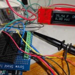
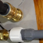
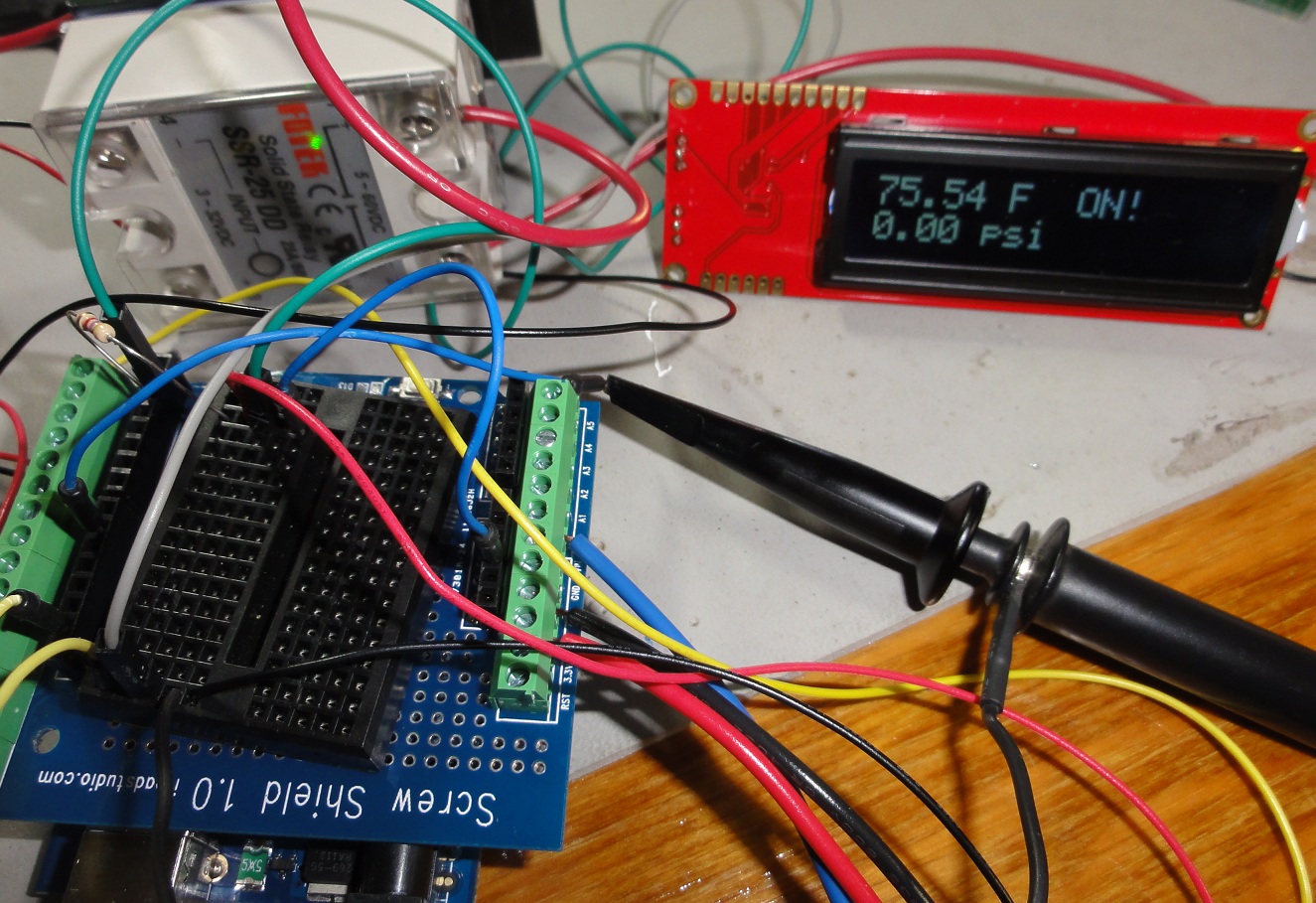
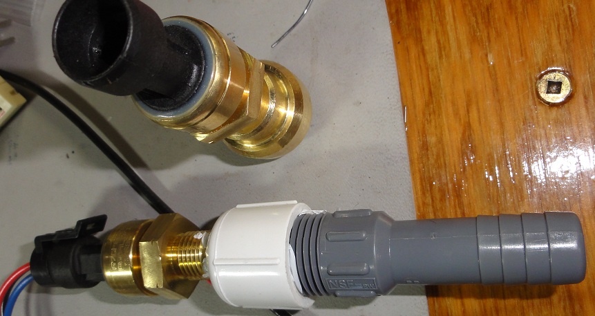
I’ve started making some headway on this. I have an LCD displaying status, and I picked up two Sensata 67CP sensors on ebay. These Sensata sensors are probably for a hydraulic application, my friend John thinks. The smaller threading is 5/16-24. I purchased a brass PEX end cap, drilled, and tapped it for this sensor. The output at 0psi (sea level) hovers about 1.3 volts and a regression curve shows it to be linear to about 60psi.

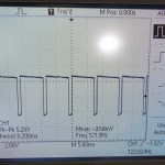
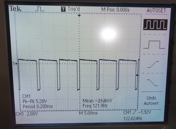
I have a DC Fotek SSR that I’m using for pump control. I’m driving the SSR from a PWM port on timer1. I’ve changed the prescalar constant to something lower that the Fotek can cleanly switch. I found out the hard way that using a digital port on timer0 messes up the serial output to the LCD.

DSC02251

DSC02252

DSC02253

HC-SR04 wiring harness

Tonight I started creating the four-wire harnesses for GND, VCC, TRIG, and ECHO for the $4 ultrasonic sensors. I created fie sets for each of the front-facing sensors. This will be the first test of using the Mega to gather data, then send to the BeagleBone. I verified with the maker’s of RoboClaw, that it uses 3V TTL serial. This means no level converter will be necessary to interface it with the BeagleBone.

Found an interesting open source website for SLAM: OpenSLAM. It will take some time to dig through the project and see if anything is usable.

Blu lipo batteries

Tonight I soldered Deans connectors on some “Blue” brand lipo batteries. I have two of these, one for the Arduino, and one for the motor system. These have a much higher amp/hour rating than AA’s, and will quickly repay the investment after several charges.