Epiphyte Build Update #2

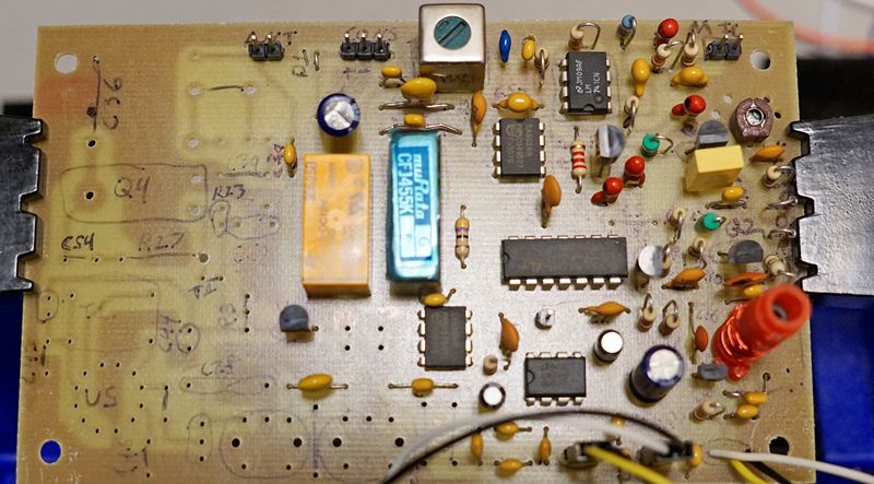
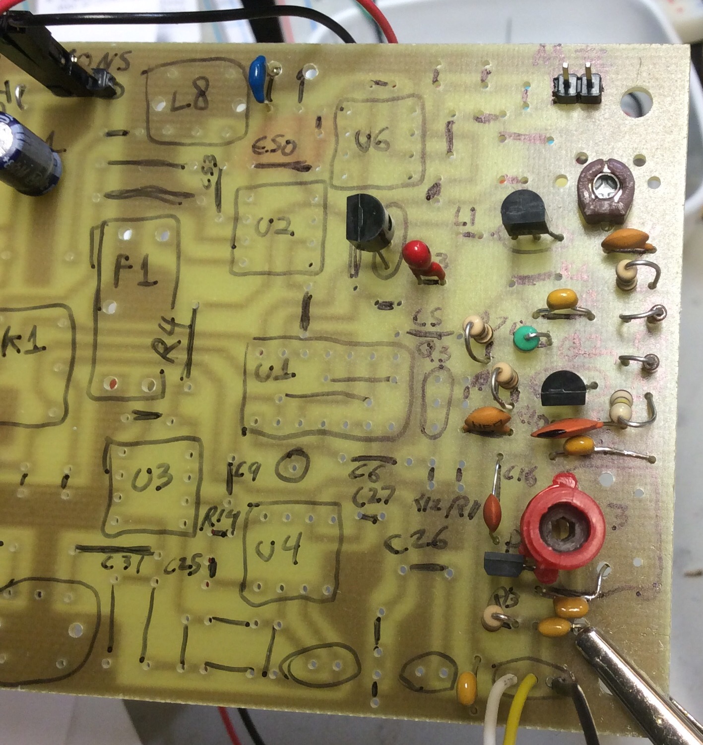
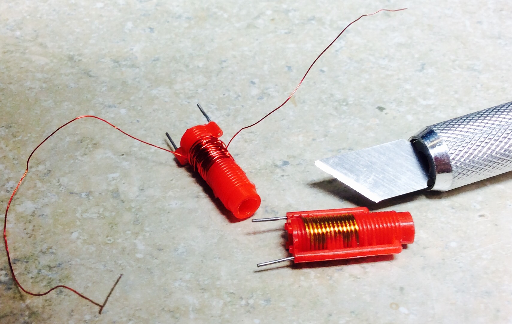
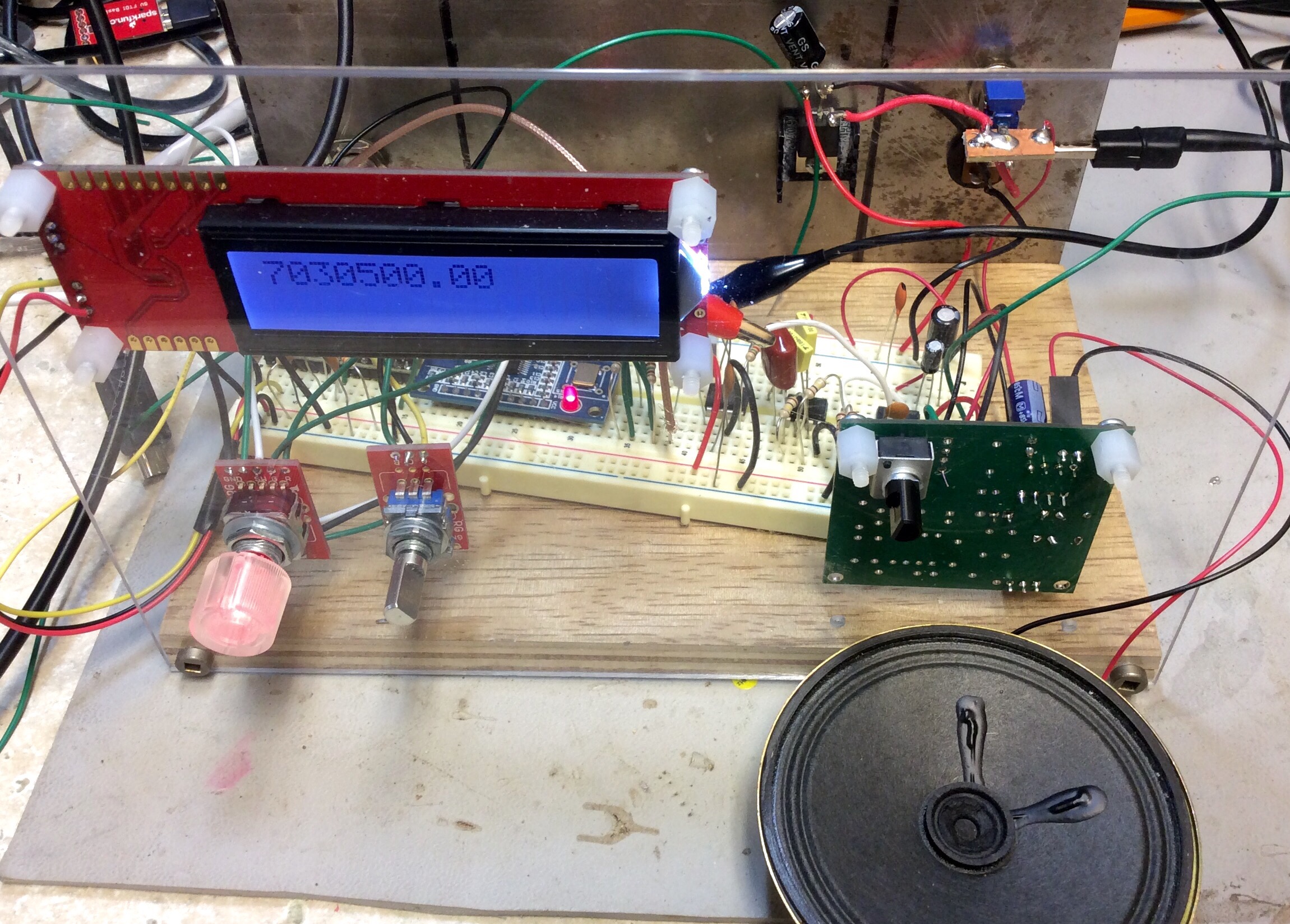
I located a suitable (and cost effective) IF filter from China on ebay. It took me 3 months to take delivery of this part. The part was pulled from some existing piece of equipment. I’m substituting a murata CFJ455K  for the original IF filter. The only difference is the case is ~2mm longer. Unfortunately, this means it’s not pin compatible with the original drilled holes. The pcb has the space to drill new holes and drop the filter in.

I had not expected the IF filter to be easier to find than the CA3020A. I’ve made five purchases of this unit on Aliexpress, and not a single one of the sellers actually has one. If one is willing to pay $35 to $50, luck might be better. At this point, I”m thinking that a custom drop-in amplifier may be a better approach. A simplified push pull amplifier with a buffer will probably suffice as not all capabilities  of the CA3020A are used.

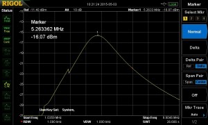
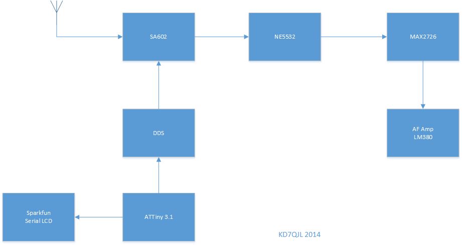
The receiver portion is mostly finished. The LO and VFO are aligned. The LO output is too high, it will need to be reduced by changing the value of C5.


epiphyte with murata filter

Failed SOTA attempt “The Twins” W7O/CM-013

My Friend Bruce and I decided to do a late fall camping trip at Waldo Lake in the Oregon Cascades. There are a several peaks that qualify for SOTA; “The Twins” W7O/CM-o13 was closest and had a trail to the summit. This peak is 7360′ in elevation. It has a smaller, false summit that is several hundred feet shorter.

We camped in the public campgrounds around Waldo Lake and left about 10am Monday morning. It snowed lightly the night before and was pretty cold. Temperatures were no higher than 32F at that time.


the twins real summitIt took us until about 1pm to reach the false summit. At that point there was 2-3 inches of snow on the ground. We lost the trail at this point and debated turning around.


the twins topo

We pushed ahead and bushwhacked our way around the rim, through the exposed snowfield leading up to the summit. At this point visibility dropped to a few hundred yards. There was 4-5 inches of snow on the summit.

We found a sheltered spot on the summit that shield us from the 20+ mph winds. Bruce and I assembled the Buddipole in a 20m vertical configuration. Bruce bravely volunteered to hold it. This was my first trip in the field with my KX3. I lugged a 10ah LiFePO4 battery along. I ran the KX3 at 10 watts power output. The noise on 20m was relatively low at S2-S3. We could hear a lot of stations, but had a hard time getting the signal out. We managed three contacts on 20m before the temperature started dropping.

About 1400 the temperatures got cold enough I lost dexterity in my hands we decided to pack it up and start out descent. We spent about an hour on the summit and saw at least an inch of snow accumulation. We took our time coming down and warmed up a bit. Overall this was a seven mile hike with about 1700 feet of elevation gain.

KL7HM AZ
AL4Y AK
W0RW Pike’s Peak, CO


the twins trail sign


bruce trail


small lake


bruce final ascent the twins


Josh summit the twins


EARCHI end fed


The new house is in a small development with a HOA. There is enough space in the backyard for a stealth antenna, but not enough length for a dipole. With all the talk on QRP-L, I decided to built an EARCHI end-fed antenna. I really want the 20/17/15 bands. My two story house is about perfect height to meet the minimum 1/4 bandwidth above ground. I used a T130-2 from partsandkits.com.
IMG_0626.JPG


IMG_0627.JPG


Starting the Epiphyte 2 Build

I’ve been thinking of buying a KD1JV 75m “Survivor” ssb radio kit. I came across the precursor to the Survivor, the Epiphyte. Derry Spittle VE7QK, now a SK originally designed the Epiphyte in the early 1990’s. The Epiphyte uses several now obsolete parts to reduce total parts count. Most notably a CA3020A and a Murata M455J1 ssb bandwidth filter. I’ve sourced the CA3020A cheaply from China. The M455J1 is harder to find. Occasionally, you see some on ebay for about USD$60. I purchased a PCB from Far Electronics for USD$10.

I’ve got the VFO section working. I substituted a VHF inductor that I rewound with 20 turns of 26AWG to get about 1.7uH. The MVAM108 can still be purchased easily from any store that sells NTE replacements. Look for NTE618. I found mine at Fry’s.


Turning vhf inductors into HF friendly coils

Many years ago I bought a bulk lot of these red slug tuned inductors off ebay. They present an inductance of less than one uH, so they were probably used somewhere in a VHF radio.

As an experiment, I cut off the windings, and wrapped my own 28 awg winding on it. I was hoping to create a variable inductor in the 3.7 uH range for an Epiphyte 2 radio that I’m collecting parts for.

I would about 30 turns on it, and tested the start to end inductance range while moving the slug. With 30 turns, I can get 3 uH to about 7 uH. The pigtails can be wrapped around the legs and soldered.

I tested the Q using a 100pf capacitor, and came up with a value of 205.


IMG_0539.JPG


red inductor serials LC spectrum analyzer screencap


3D printed brackets

I designed and printed these brackets to hold a Western Mountain Radio PWRbrite. This is a LED strip light that runs off 12VDC and uses PowerPole connectors. It may have come with with zip ties at one point, but those are now long gone.

This is part of my journey learning to use OpenSCAD.


mount(30, 40, 18, 5, 20);

module mount(width, height, hole, mount_width, flange)
{

difference() {
cube(size = [mount_width,height,width], center = true);

translate(v=[-3,6,0]) {
rotate ([0,90,0])
cylinder(r=hole/2, h=mount_width+2);
}
}

difference() {
translate(v=[0,-height/2,-15]) {
rotate ([0,0,90])
cube(size = [mount_width,flange,width]);
}

translate(v=[-2*flange/3, -width/2+1, 0]) {
rotate ([90,0,0])
cylinder(r=3, h=mount_width+2);
}
}
}

Building a 40m ARRL Band-Pass Filter

Since I purchased the MiniVNA, I’ve been playing with Elsie and building band pass filters. A restricted version of Elsie is provided free of charge. The restricted version has more than enough power to do 99% of what an amateur radio home brewer could ask for. There is a pretty steep learning curve to doing a theoretical design with Elsie, then actually building it. Taking an putative design and matching it to capacitors that one has on hand and inductors that can actually be created (the winds fit on a given toroid).

As part of the learning process, I went back to one of the ARRL articles (linked at the bottom) that provided a table of values for each band. I breadboarded a 40m band pass filter, then used the MiniVNA to examine it’s phase and frequency characteristics. The final step was experimentally determining the output of the output RF impedance. This is done by placing a 50 Ohm Feed-Thru Coaxial Terminator between the scope probe and the scope. This uses the principle of a voltage divider given at least one known load value to calculate the impedance. Here is an article with online calculator for this topic. I calculated the built band pass filter at 53 ohms.

40m bandpass

(null)

Article Links:

Working SI5351A Breakout Board

After Jason NT7S wrote about the SI5351A clock generator, I purchased several of his Rev B designed prototype boards by Oshpark (Portland local–yeah!). I spent quite a few hours getting these things to work. The SI5351A is a msop footprint. Mounting this chip turned out to be a very tricky exercise. Every time I thought I got all the pins correctly soldered, I would go back and check with a DMM and find one that was not actually conductive.

There are a few other tricks to making the NT7S board work correctly:

  • Read Jason’s documents. He has written a lot of documentation and everything is there you need to know. You just to need read it thoroughly. I did not and it took hours of troubleshooting to figure out what he already documented.
  • Pay attention to Jason’s notes about using an ECS crystal. Pins 2 and 4 are connected and will short Vdd to ground.
  • The SI5351A chips I got from Mouser use the I2C address: 0x6F
  • Capacitor C3 on the output of the LP2985 is required to get the 3.3 volt output. Omitting it will cause the local supply voltage to be around 4 volts.

If you want a general purpose SI5351 to play with or for simple non RF purposes, the Adafruit breakout board (PN 2045) can be purchased assembled for cheaper than I can buy the parts. The NT7S board is thought out and more agile. It has better mounting holes, configurable I2C pull ups (I really appreciate this), provisions for VCXO and isolation transformers.

I really appreciate the work that Jason has put into characterizing this device. He single handed opened the doors for a lot of people to start using this device and it’s become the talk of QRP-L, EMFRD, and SolderSmoke.

IMG_0467.JPG
(please excuse my horrible soldering job. I had to cannibalize some SMD parts from an ActionTec router)

HF Radio Prototype Platform

Now that I have some vacation time, I’ve been working on my radio prototype platform. The long-term purpose is to provide a place to work on the software filtering algorithms. I added an audio stage to prototype using a MAX2726 5th order filter. Using a 68pf external capacitor, I get nice roll off about 1.2khz.

block diagram

IMG_0462.JPG