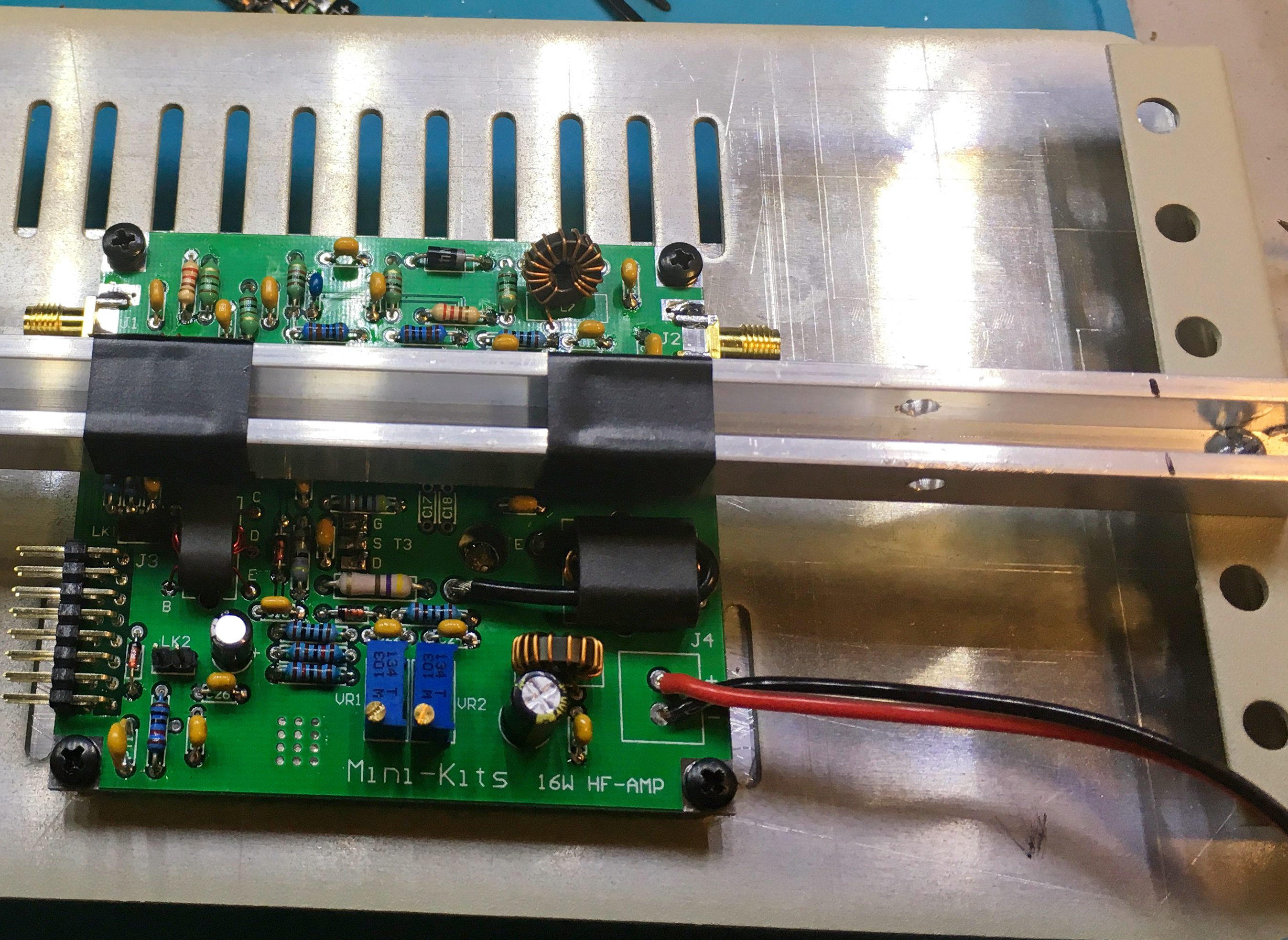
After the pcb was finished (minus the power MOSFET), the heat sink needs to be drilled and tapped for to mount the standoffs and the MOSFET pair. Source a 150x80mm heatsink on Amazn. The bottom is at least a quarter inch thick. I’m using M3-0.5 standoffs for all pcb mounting. It’s actually pretty hard to find a 2.5mm drill bit. I tried a metric tap set from Dubro, but snapped the bit in the first minute. I ended up purchasing a 40 pack (cheap imported bits). These bits performed way better.
Build Log: RF Final Power Amplifier for the M1 Transceiver
I’m doing a lot of product R&D on my bench, so the M1 took the back seat for a while. I broke out the RF power amplifier kit. The EME210 is based on the RDF16HHF1 mosfet. The power amp assembled for me in about three hours. There are only a few surface mount parts on the bottom and about six inductors to wind. It comes with M3 standoffs and screws to mount to a heat sink. I purchased a 150mm by 80mm heatsink on Amazon.
I also spent the time to get the AGC/IF through audio amplifier stage aligned. At this point I really need logic control of the boards. I have a design for I2C based control of the system via the builtin 16 pin wiring harness. More on that soon.
Bourns Optical Rotary Encoder Final Assembly
The new circuit boards for the break-out board I designed arrived. The assembled version checks out just fine with the interrupts enabled using the PJRC Encoder library.
I’ve struggled finding the perfect tuning knob to use this encoder on my [ongoing] M1 Transceiver build. Eventually, I decided the best thing to do would be to buy another Elecraft K3 tuner knob directly. Bottom picture shows it perfectly.
I2C Controlled Tactile Buttons
Sparkfun carries these nifty LED illuminated tactile buttons (SKU COM-10439). The LED’s are controllable separate from the push button action. Using them for real projects is pretty hard, especially if you have a case. In order to solve this, I devised a circuit board that has mounting holes, so these can sit up on a case.
But why stop there? For each button, you use two pins on your MCU. Then you need additional parts to do debouncing, pull ups, etc. Add a MCP23008 I2C expander, and you can control several push buttons over an I2C bus. This chip operates from 3.3V and 5V. It has wide support in the Arduino community.
Si5351 PCB with Low Pass Filter
In today’s mail, the latest revision to my Si5351 board arrived from pcbs.io. For me, this board is really a prototype and proof of concept. It is a reusable building block. This module is streamlined I can import it into a larger design in KiCad, remove the headers, and go. The low pass filter is really designed for HF work. One could change the values and reformulate the lpf.
After the kids go to bed, I salvaged the parts from the last generation board and assembled one. It is always thrilling when it works right off the bat. This generation fixes a VCC problem, adds additional bypass capacitors, an extra [optional] header for using outputs two and three. Lastly, lots of markings (documentation on the board).
Evaluating the Si8540 Current Sense Amplifier
I needed a current sensor for another project. I found the Si8540 in Mouser’s catalog. It requires a very low resistance sense resistor. The output voltage is in the zero to 3V range. The Si8540 comes in a SOT-23 package and costs US$0.55/piece in single quantities.
I fabricated a prototype board that has holes large enough to solder 14 awg wires for load and source. Like most of my prototype boards, this one had a flaw in it (as seen by the jumper). Including the pcb, this board cost me less than US$2.00.
Using a current limited supply and some high wattage resistors, I compiled the data to chart the performance over a 3 amp load. The low of end of the current sense is skewed. The datasheet talks about the typical error at 1% of Full Load being 5% to 10%.
Build Log: M1 Transceiver: Wiring the Receiver
The last two days I’ve spent laying out the receiver and common IF portions of the M1. I’m basically copying the Minikits suggested layout for the Hammond case. The aluminum sheet divides the inside of the case. The common IF subsystems and receiver modules fit on the top. The DDS and modulator components fit on the bottom. A number of the boards stack.
I purchased a coax crimping tool for RG-316. All the coax jumpers are of my own creation. This cuts down the cost as those jumpers can be quite expensive for quality ones. The SMA jacks and connectors are from China. The jacks rated for a whopping 500 connections! I doubt I’ll hit that ceiling for this project.
Soon, the receiver will be ready for power-on tests and alignment. The front-end mixer has a pad on the LO input, so a Si5351 at the lowest power level will be enough for to play with it.
Build Log: M1 Transceiver: 9mhz Notch Filter, IF Attenuator, and IF Amplifier
Bourns Optical Rotary Encoder PCB
I purchased a Bourns ENA1J serial rotary optical encoder. This control has a nicely weighted shaft that uses ball bearings. It is rated for >= 10 million rotations. The ENA1J outputs beautiful square signals (unlike mechanical rotary encoders). I think I paid USD$35 for this premium part. You will find optical rotary encoders on high end radios like the Elecraft K3 and professional mixer boards.
I designed a pcb that takes the quadrature output of the ENA1J into INT0 and INT1 inputs of the ATMEGA328P mcu. A pin header gives access to the I2C bus that allows this to be used as a satellite peripheral.
Filtering the Si5351 Output
I’m working on building blocks that can be used for larger designs. One of those building blocks is a DDS signal generator using the Si5351. I added a low pass filter to the output of CLK0. This filter starts rolling off at 50mhz. Elsie generated the schematic and I normalized the values to smd capacitors I had and Murata rf chip inductors I purchases.
L1, L2, and L3 are smd inductors that cost about USD$0.20 each.
Here is what the Si5351 output looks like with Adafruit’s example library sketch.
This is the output after the low pass filter. Second and third harmonics are still there, but there is definite improvement.