MAX11115 ADC with a Particle Photon

Maxim makes this small ADC that comes in SOT23 and other packages. The cost runs from $1.65 to a few dollars depending on if you choose 8, 10, or 12 bit variants. They boast sample rates up to 2 or 3 mega samples per second. These are 3V only chips. They are not 5V tolerant. This should make it easy to use with ARM or Raspberry PI boards.

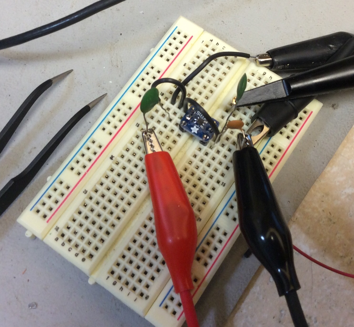
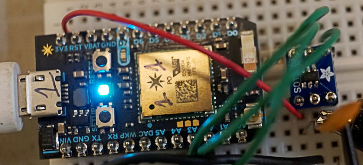
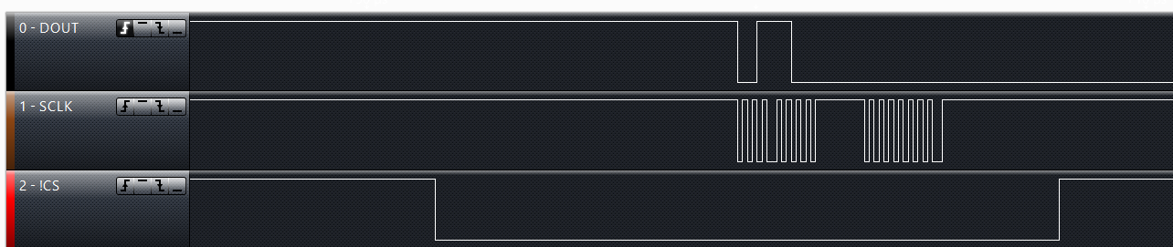
I wanted to verify this work and get some proof of concept code. I chose to use the MAX11115AUT+T that I soldered onto an Adafruit SOT23 breakout board. The ADC can communicate use several digital protocols including SPI. It only takes three wires to control it: SCLK, MISO, and !CS.  When CS goes low, the SPI clock drives the digitizing of the signal. After one clock, the first bit is available on DOUT. An new bit is available each clock pulse. The ADC always writes two bytes out. If you are using the 8 bit ADC, you still need to read in the second byte.


MAX11115 ADC copy


MAX11115 timing


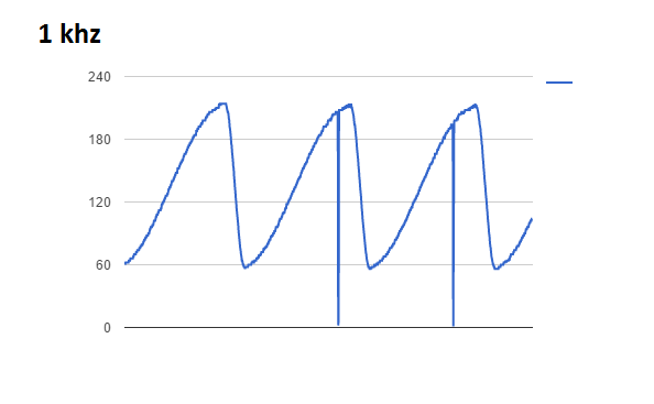
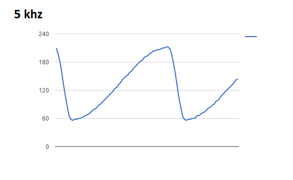
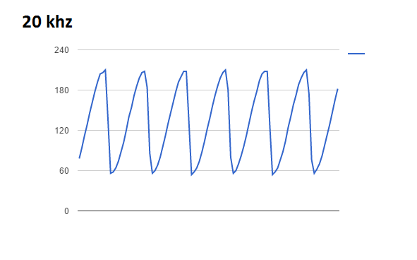
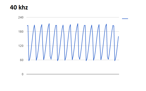
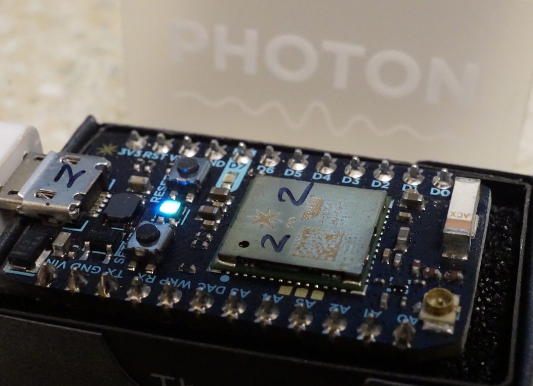
To test the sample rate, I wrote some code on the Particle Photon that reads in 100 samples, stores it in a buffer, then transmits it over TCP to a local python server. A signal generator is feeding the ADC a sine wave. Here is what the raw data looks like at various input rates. Please keep in mind this is a quick proof of concept. There is no buffering, impedance matching, or anti-aliasing. The SPI bus is running at Photon’s default clock speed.


MAX11115 1khz MAX11115 5khz MAX11115 20khzMAX11115 40khz


Particle Photon has Arrived

My batch of Particle Photon’s arrived on June 27.

I also have a first gen Spark Core. The software stack is much more mature now. Compared to the Spark, the Photon’s are a breeze to setup. They download the latest firmware quickly, and come online. I used my iPad Air to do the associations, the iOS app is much easier to use. Why use an arduino, when you can have ARM power and WiFi for $19.

particle photon

Starting the Epiphyte 2 Build

I’ve been thinking of buying a KD1JV 75m “Survivor” ssb radio kit. I came across the precursor to the Survivor, the Epiphyte. Derry Spittle VE7QK, now a SK originally designed the Epiphyte in the early 1990’s. The Epiphyte uses several now obsolete parts to reduce total parts count. Most notably a CA3020A and a Murata M455J1 ssb bandwidth filter. I’ve sourced the CA3020A cheaply from China. The M455J1 is harder to find. Occasionally, you see some on ebay for about USD$60. I purchased a PCB from Far Electronics for USD$10.

I’ve got the VFO section working. I substituted a VHF inductor that I rewound with 20 turns of 26AWG to get about 1.7uH. The MVAM108 can still be purchased easily from any store that sells NTE replacements. Look for NTE618. I found mine at Fry’s.


Turning vhf inductors into HF friendly coils

Many years ago I bought a bulk lot of these red slug tuned inductors off ebay. They present an inductance of less than one uH, so they were probably used somewhere in a VHF radio.

As an experiment, I cut off the windings, and wrapped my own 28 awg winding on it. I was hoping to create a variable inductor in the 3.7 uH range for an Epiphyte 2 radio that I’m collecting parts for.

I would about 30 turns on it, and tested the start to end inductance range while moving the slug. With 30 turns, I can get 3 uH to about 7 uH. The pigtails can be wrapped around the legs and soldered.

I tested the Q using a 100pf capacitor, and came up with a value of 205.


IMG_0539.JPG


red inductor serials LC spectrum analyzer screencap


Building a 40m ARRL Band-Pass Filter

Since I purchased the MiniVNA, I’ve been playing with Elsie and building band pass filters. A restricted version of Elsie is provided free of charge. The restricted version has more than enough power to do 99% of what an amateur radio home brewer could ask for. There is a pretty steep learning curve to doing a theoretical design with Elsie, then actually building it. Taking an putative design and matching it to capacitors that one has on hand and inductors that can actually be created (the winds fit on a given toroid).

As part of the learning process, I went back to one of the ARRL articles (linked at the bottom) that provided a table of values for each band. I breadboarded a 40m band pass filter, then used the MiniVNA to examine it’s phase and frequency characteristics. The final step was experimentally determining the output of the output RF impedance. This is done by placing a 50 Ohm Feed-Thru Coaxial Terminator between the scope probe and the scope. This uses the principle of a voltage divider given at least one known load value to calculate the impedance. Here is an article with online calculator for this topic. I calculated the built band pass filter at 53 ohms.

40m bandpass

(null)

Article Links:

Working SI5351A Breakout Board

After Jason NT7S wrote about the SI5351A clock generator, I purchased several of his Rev B designed prototype boards by Oshpark (Portland local–yeah!). I spent quite a few hours getting these things to work. The SI5351A is a msop footprint. Mounting this chip turned out to be a very tricky exercise. Every time I thought I got all the pins correctly soldered, I would go back and check with a DMM and find one that was not actually conductive.

There are a few other tricks to making the NT7S board work correctly:

  • Read Jason’s documents. He has written a lot of documentation and everything is there you need to know. You just to need read it thoroughly. I did not and it took hours of troubleshooting to figure out what he already documented.
  • Pay attention to Jason’s notes about using an ECS crystal. Pins 2 and 4 are connected and will short Vdd to ground.
  • The SI5351A chips I got from Mouser use the I2C address: 0x6F
  • Capacitor C3 on the output of the LP2985 is required to get the 3.3 volt output. Omitting it will cause the local supply voltage to be around 4 volts.

If you want a general purpose SI5351 to play with or for simple non RF purposes, the Adafruit breakout board (PN 2045) can be purchased assembled for cheaper than I can buy the parts. The NT7S board is thought out and more agile. It has better mounting holes, configurable I2C pull ups (I really appreciate this), provisions for VCXO and isolation transformers.

I really appreciate the work that Jason has put into characterizing this device. He single handed opened the doors for a lot of people to start using this device and it’s become the talk of QRP-L, EMFRD, and SolderSmoke.

IMG_0467.JPG
(please excuse my horrible soldering job. I had to cannibalize some SMD parts from an ActionTec router)

HF Gain of the SMA3107 MMIC RF Amplifier

I found these surface mount rf amplifier’s on Mouser. They have no minimum stated frequency floor but are documented to work up to several (2.8) ghz. They are available for about USD$0.52 in individual quantities. The package is listed as MCPH6. The pins are closer than a SOP23. I was able to get it on an Adafruit SOP23 breakout, but it was very careful work.

I measurement the voltage gain at from 20mhz and down. The gain drops as the frequency drops. I found that SMA3107 is not really linear until about 3.2mhz. Somewhere below that it looks like some oscillation is occurring.

SMA3107 gain

IMG_0458.JPG