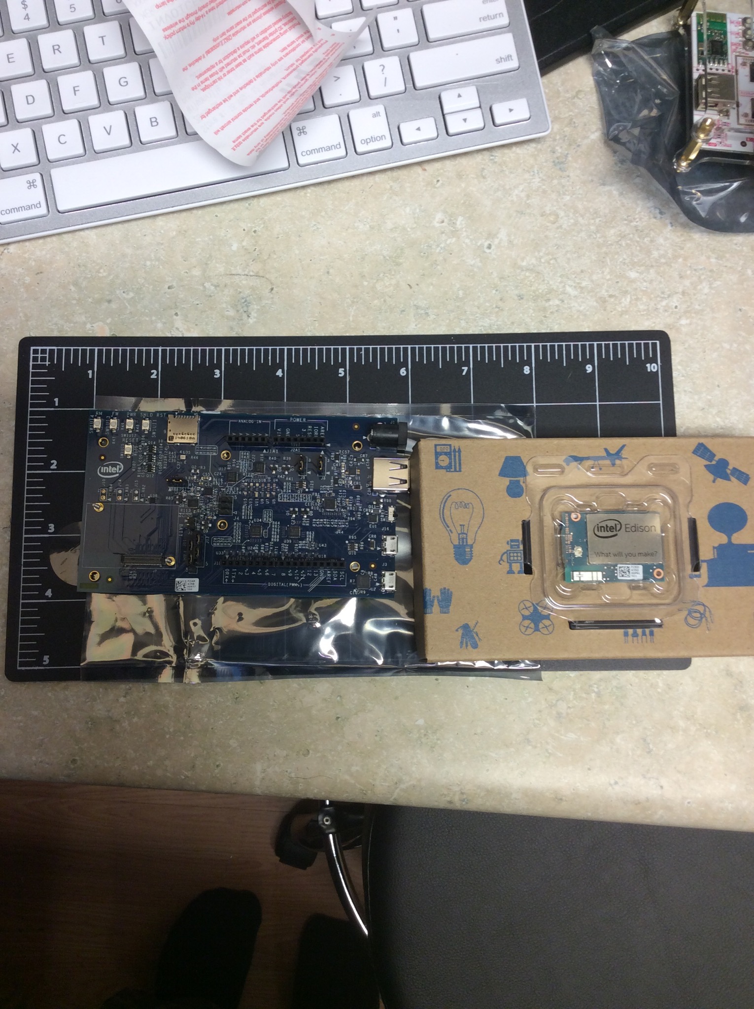
I’ve been watching the Intel Edison product line for a while. I’ve had breakout boards on backorder from Sparkfun. Found some on a shelf at my local Fry’s and could not pass it up at the price of USD$85.
software creative
I’ve been watching the Intel Edison product line for a while. I’ve had breakout boards on backorder from Sparkfun. Found some on a shelf at my local Fry’s and could not pass it up at the price of USD$85.
Super short weekend project: hookup my Sparkfun geiger counter and start reading counts per minute.
With the protective cap on (the tube will only read gamma and beta radiation) I see 6 to 16 counts per minute. I do not have a radiation source to calculate the conversion coefficient to micro Sieverts.
On a side note, I attached the board on a VMware ESXi machine and read the raw data with a python script. I’ll create a feed here soon.
I’m working on a test bed transceiver. I’ve wanted something that is modular enough, that I can swap in and out sections to test new designs (and just have fun). This is a Teensy 3.1 with a cheap Chinese DDS board that contains an AD8550. I am using one of my LM380 audio boards, a Sparkfun Serial two line LCD, and a few rotary encoders for tuning.
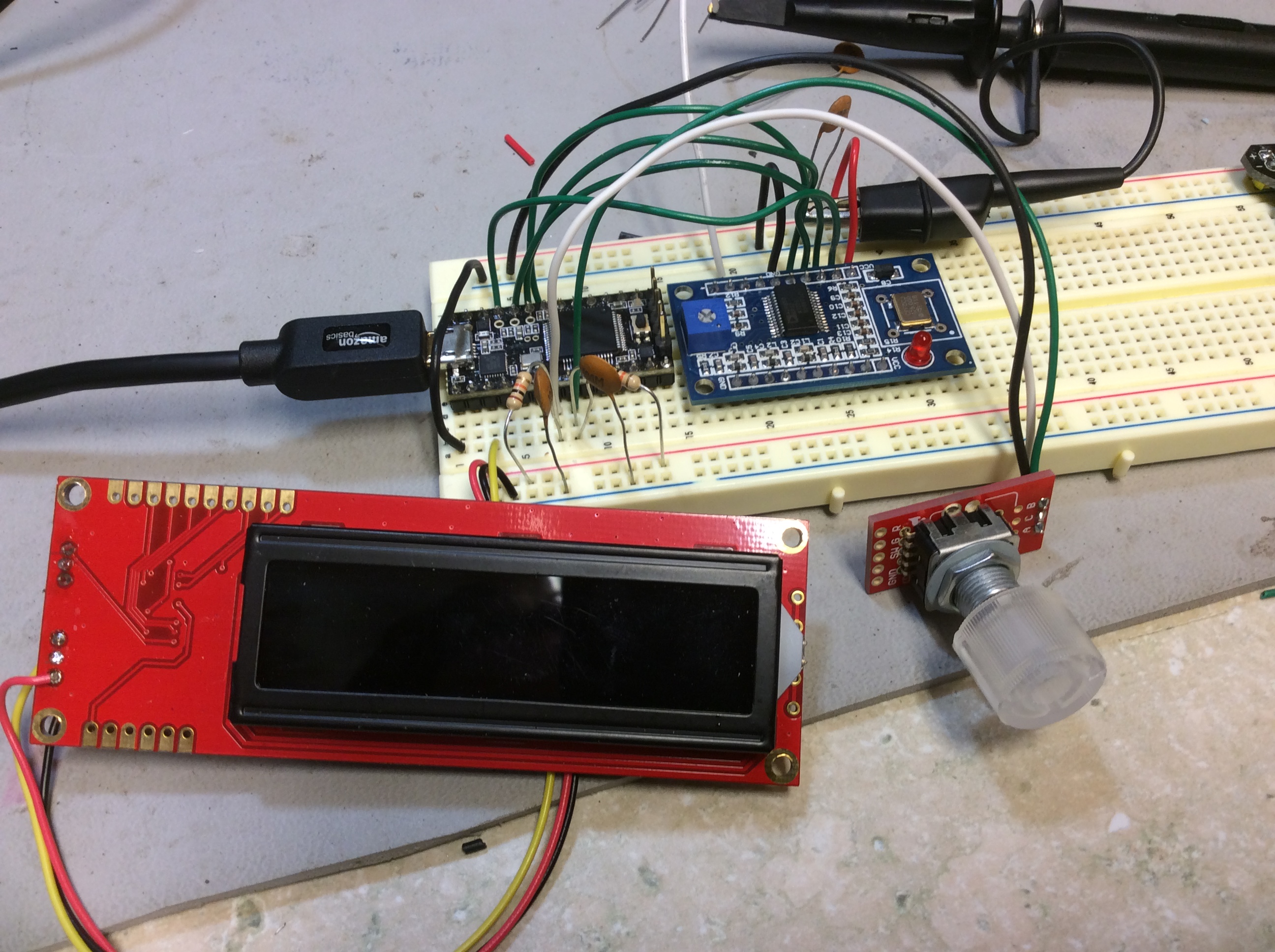
Ever since I learned that Atmel bundles a ROM bootloader that allows a FLASH program to be loaded via serial without any JTAG hardware, I’ve hankered to program and run an ARM chip from bare metal. Just for experience.
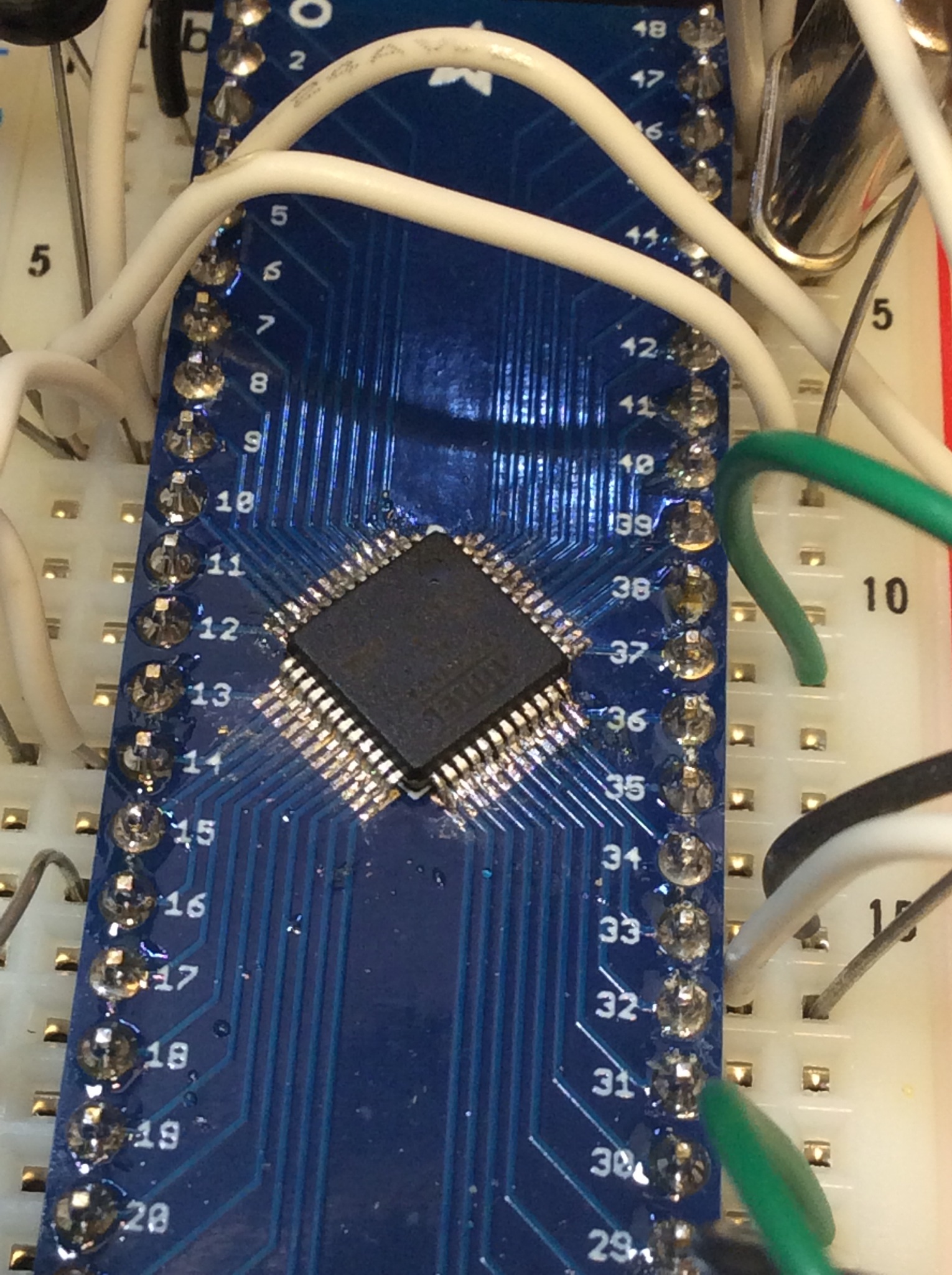
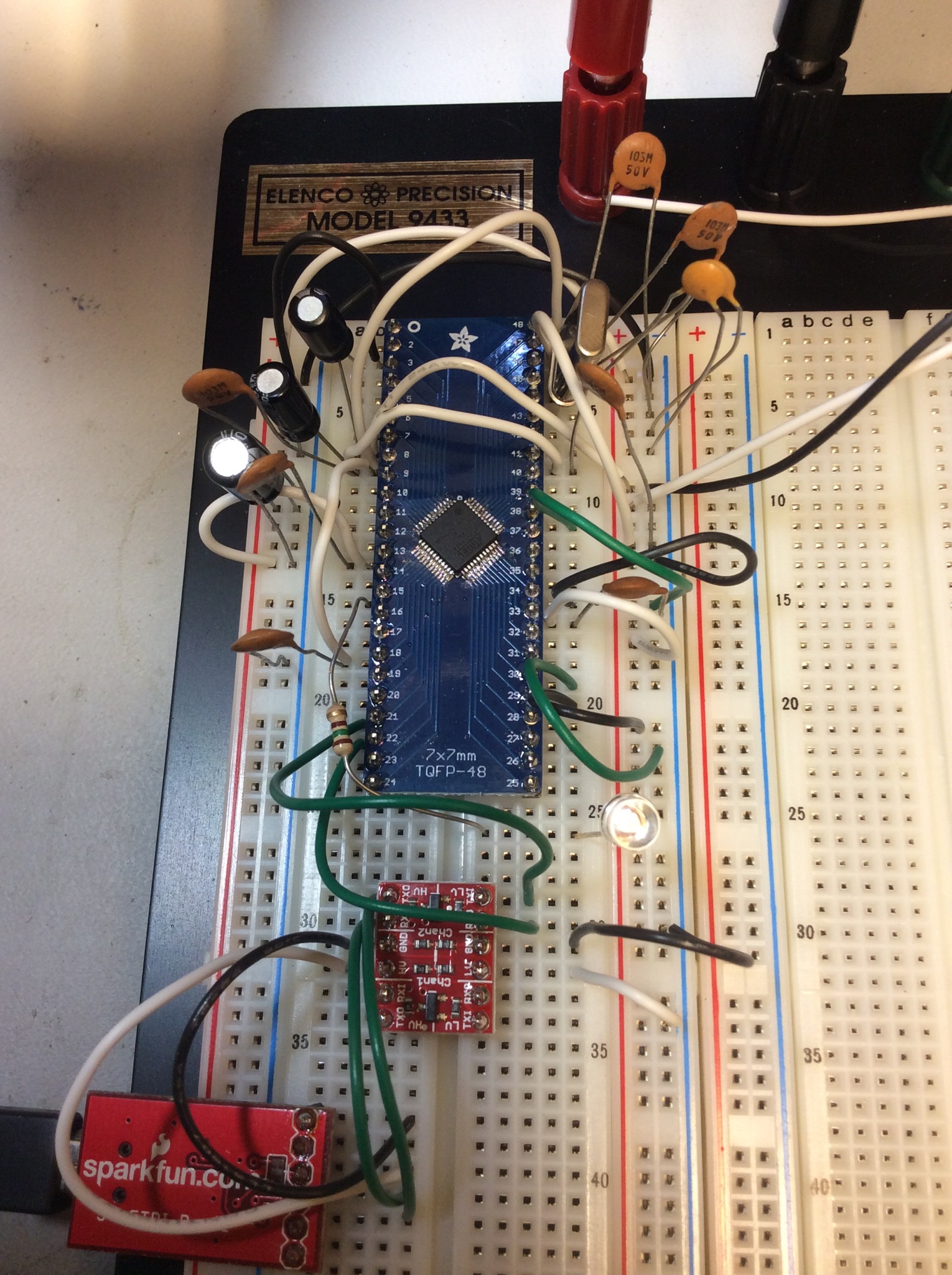
I choose a “cost effective” SAM3n2 variety in a LQFP-48 footprint. These cost $3 to $4 in single unit quantities from Mouser. I stock every variety of Adafruit SMT adapters. So it was only natural that I solder the SAM3n2 to the Adafruit adapter, then build up the circuit on a breadboard.
Several hours later one trip to Fry’s for a 0.007″ soldering tip, some cursing, a lot of solder wick I finally got the the SAM3n on my very own breakout board without any bridges. I’ve done enough surface mount soldering to know what I was getting into, but it did not decrease the amount of labor and frustration that can go into a chip with a lot of pins.
Atmel distributes the SAM-BA “SAM Boot Assistant” program that can talk to the ROM bootloader. It’s very unfortunate that SAM-BA becomes SAMBA. This makes it hard to search for help. Hey Atmel, how about using an unused acronym? SAM-BA talks to the SAM3n2 via UART0. These ARM chips are not 5V tolerant. I used a Sparkfun level shifter and a FTDI interface to connect up SAM-BA. The SAM3n2 starts off using an internal RC oscillator. You do not need to connect an external crystal. Add some bypass capacitors and everything is ready to go.
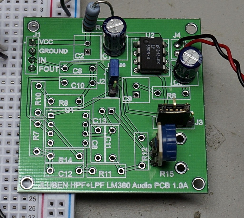
There is a minimal number of parts necessary to enable the audio amp on this PCB.
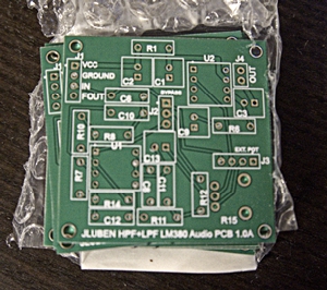
Within two weeks of placing my order with Seeed Studio, the boards arrived. They were shipped from a California address. If they are now manufacturing locally, then very cool. Mostly because it’s still cheap. Ten boards cost me $18 shipped. Friends may ask for one 🙂
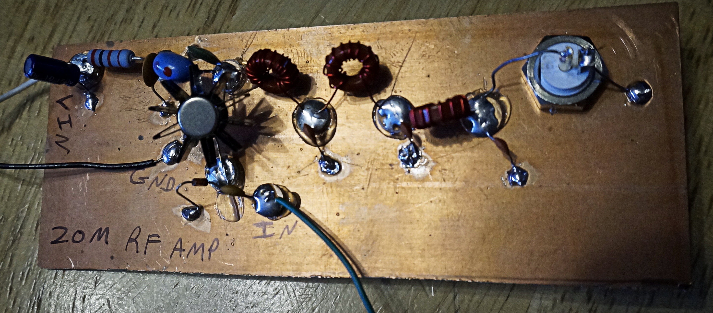
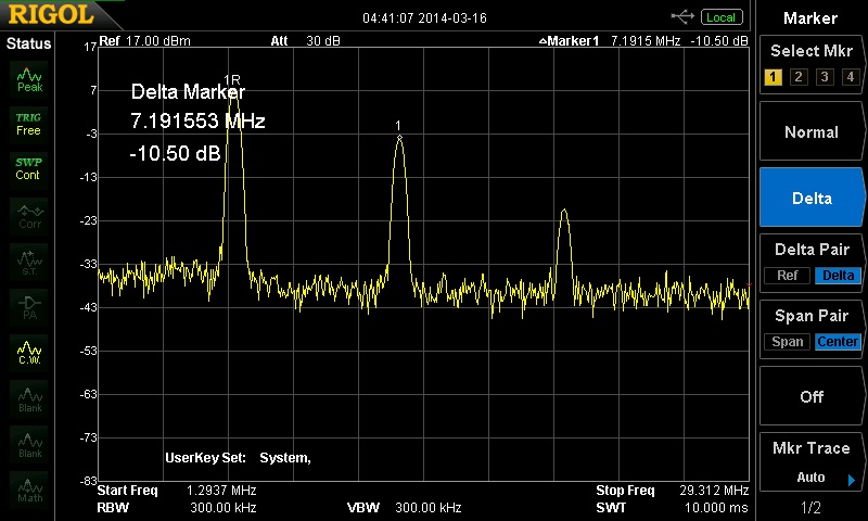
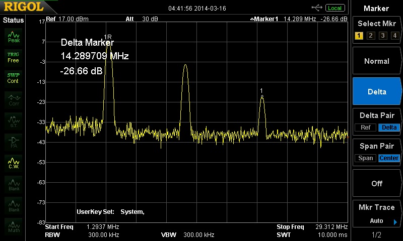
Today’s Saturday project was to solder up ugly style a 20m RF amplifier that resided on my bench for like six months. It’s been nearly a decade since I did anything ugly or Manhattan style. This project was actually an excuse to design a RF low pass filter and test it with my Rigol spectrum analyzer. The screen shots below show that the first harmonic is suppressed by 26db. Mysteriously, there is a harmonic below the primary frequency. I used a 2N3866 power transistor. This are getting hard to find, but I’ve managed to get a supply from Aliexpress.
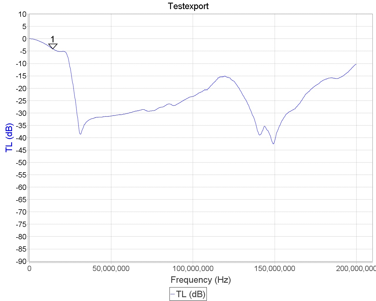
Edit 2014-12-25:
I used the low pass filter to test the miniVNA Pro. Here is what the loss response looks like:
The first draft of a modular LM380 “building block” is finished. The schematic and board layout are available on Upverter. The board fits within the 5cm by 5cm size that corresponds to Seeed Studio’s $9.99 fabrication service.
I designed this board with several features in mind:
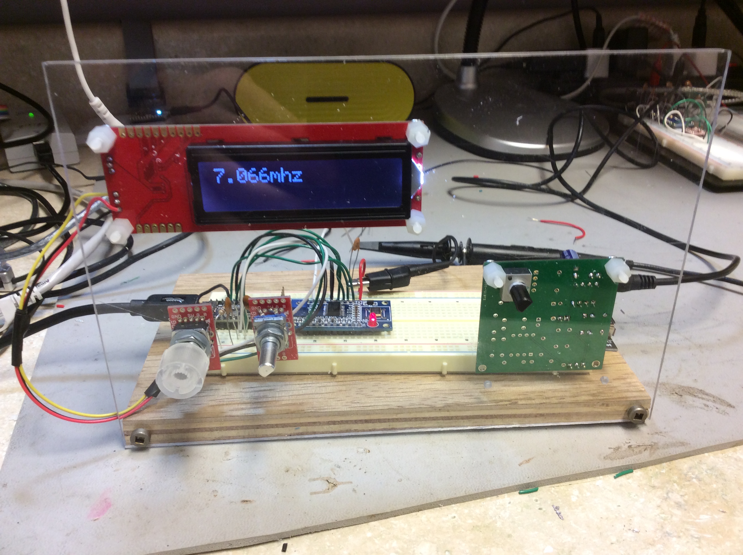
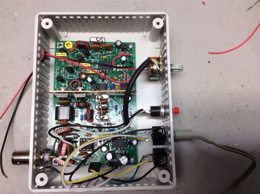
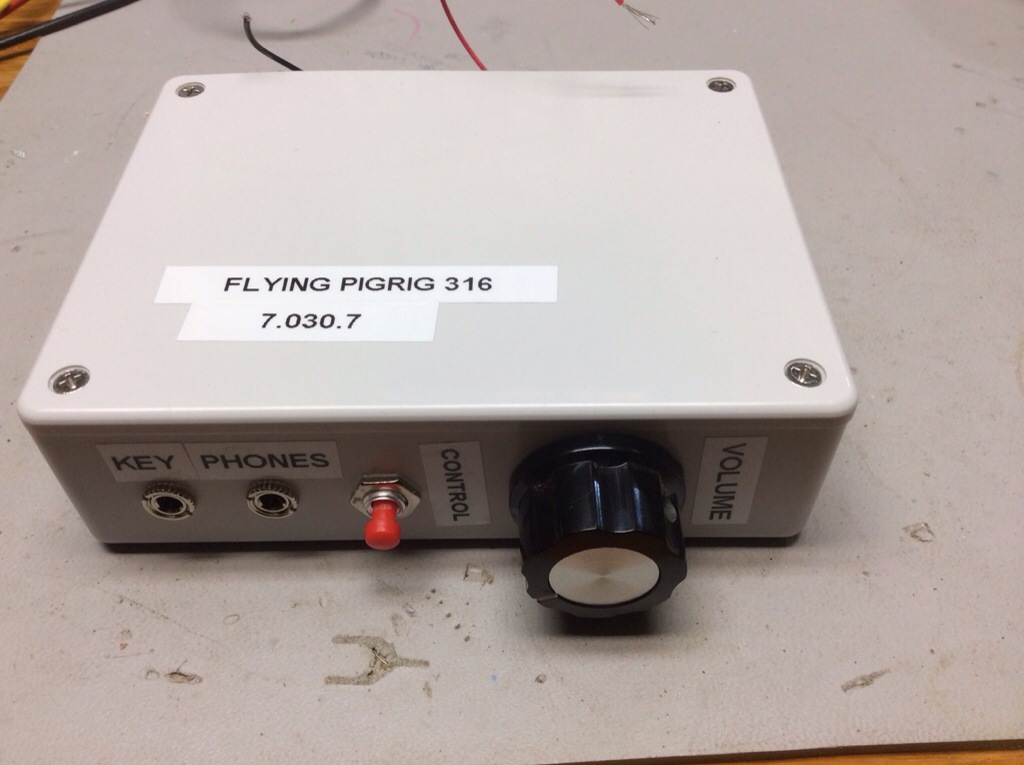
Finished up the transceiver and ran it through the alignment process. My frequency counter nor my signal generator are accurate to enough decimal places. I ended up aligning it by ear. The oscillator output is a nice clean sign wave. The output looks excellent after a quick look at the output on spectrum analyzer.
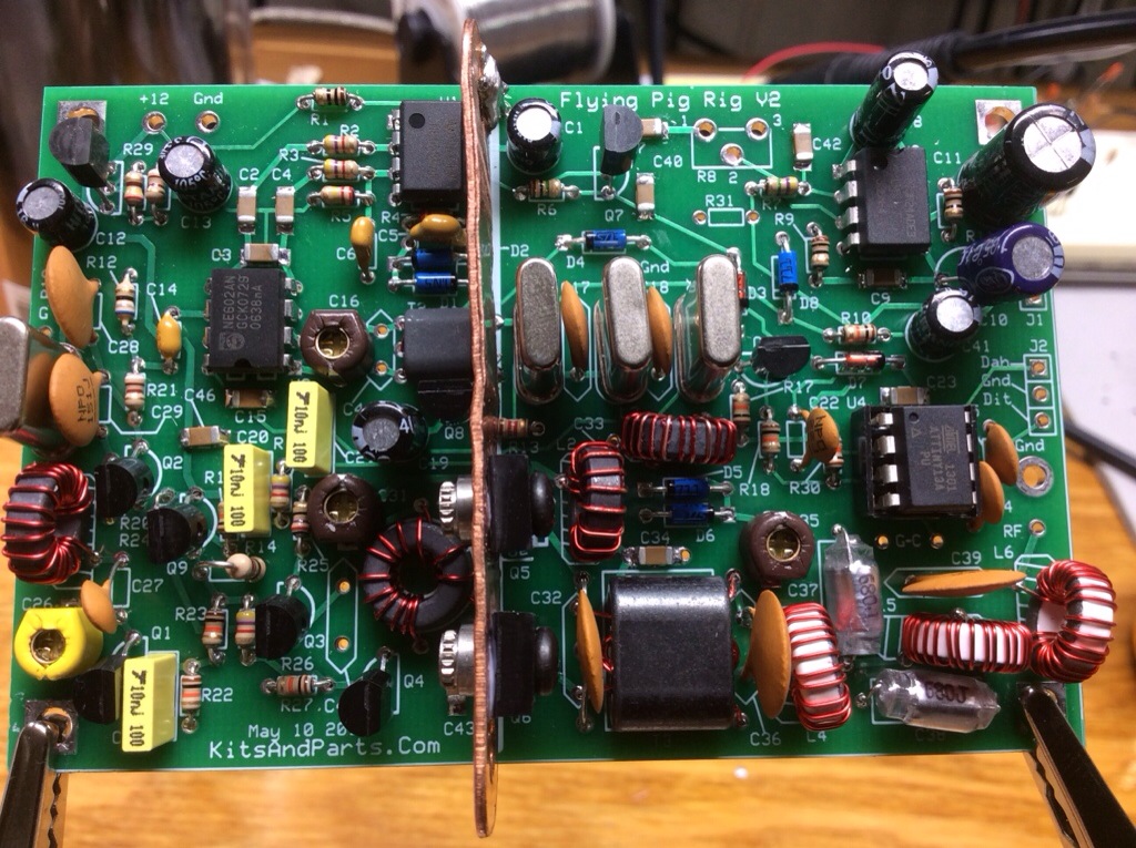
Mounted in a case. The included copper heat sink appears to be quite adequate. Still having thoughts about what type of power cable to use. My preference is Anderson PowerPole, but there are not a lot of chassis mounting options. I’m considering ordering some Anderson AutoGrip blocks from Hardened Power Systems.
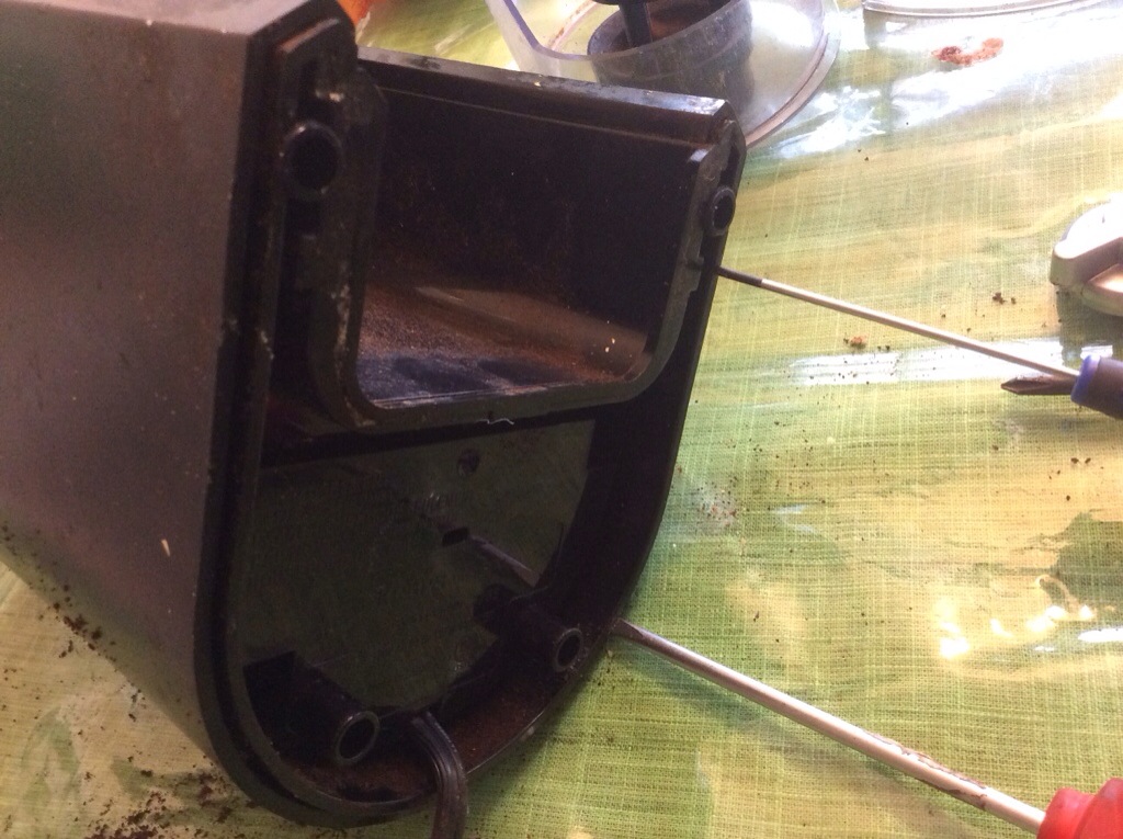
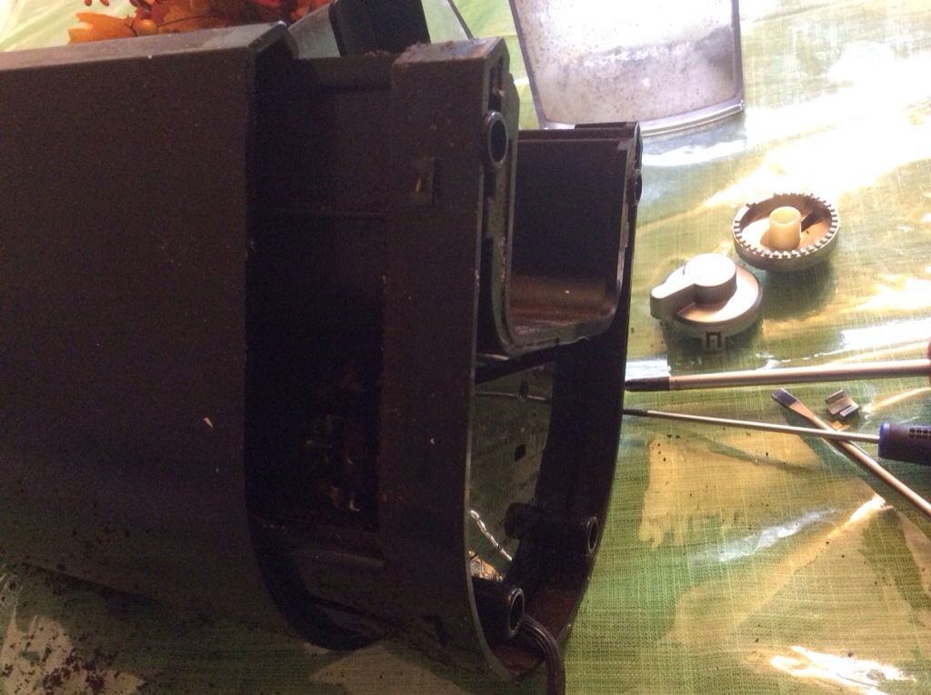
My [coffee] burr grinder finally quit on me. I’ve lived without a button on the front for quite a while. I had hopes of fixing it and saving myself some big money. It took me quite a while to figure out how to open the case–turns out to be pretty simple if you know what to look for. Using a flat screwdriver, there are four detentes on the bottom. You have to know they are there to find them.
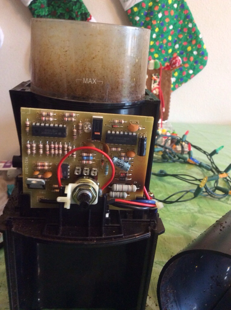
It turns out this driver circuitry is really old school. No fuses, no surface mount parts, and no isolation transformer. The driver circuit is a mix of analog and TTL logic. This thing is a fire hazard waiting to happen.
Replacing it with this Capresso model,