Since I purchased the MiniVNA, I’ve been playing with Elsie and building band pass filters. A restricted version of Elsie is provided free of charge. The restricted version has more than enough power to do 99% of what an amateur radio home brewer could ask for. There is a pretty steep learning curve to doing a theoretical design with Elsie, then actually building it. Taking an putative design and matching it to capacitors that one has on hand and inductors that can actually be created (the winds fit on a given toroid).
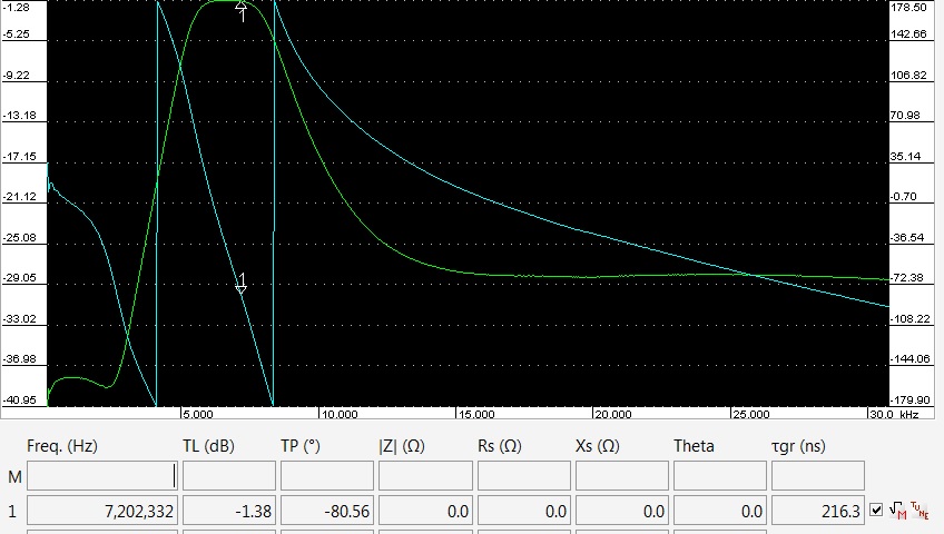
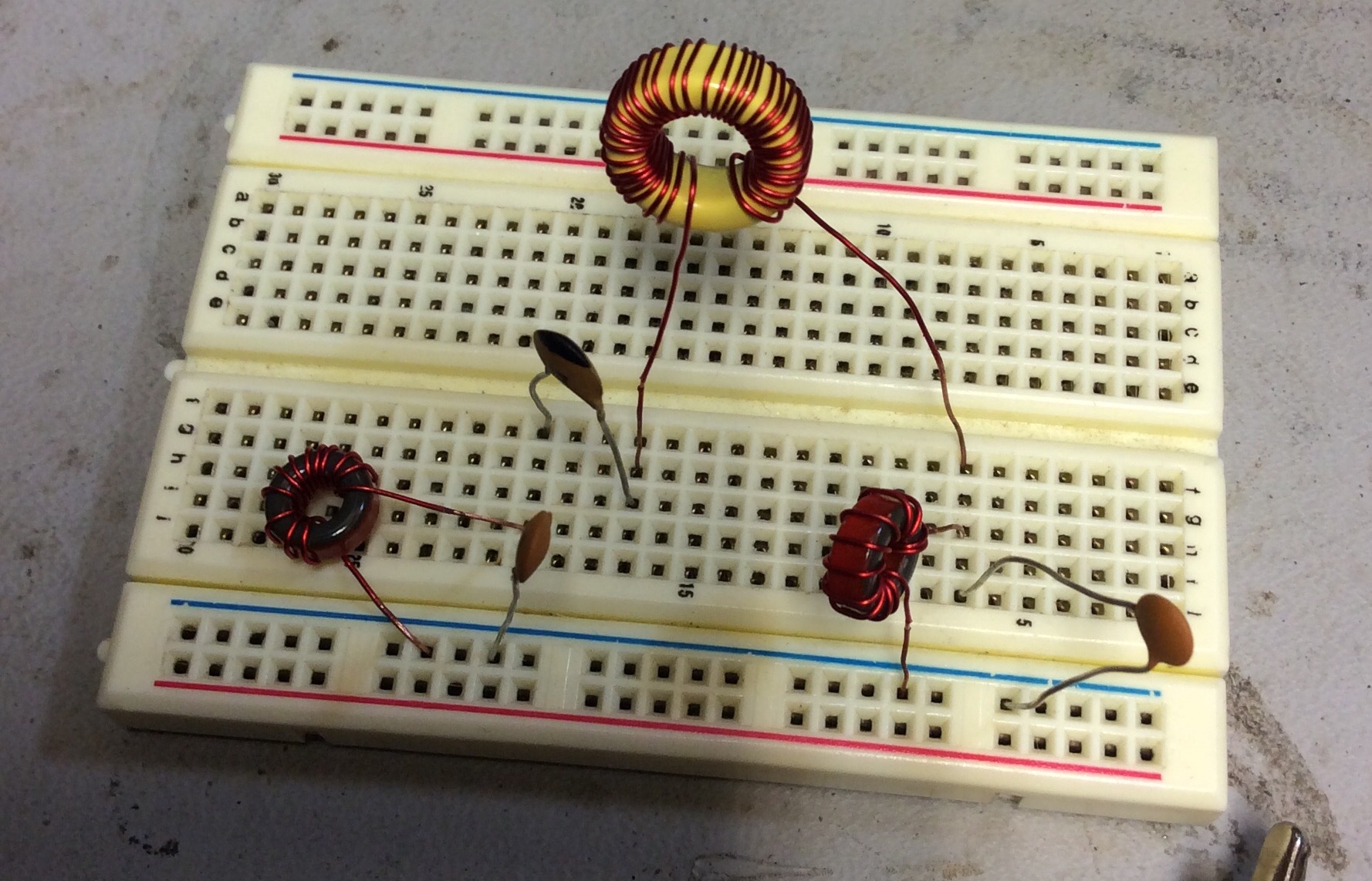
As part of the learning process, I went back to one of the ARRL articles (linked at the bottom) that provided a table of values for each band. I breadboarded a 40m band pass filter, then used the MiniVNA to examine it’s phase and frequency characteristics. The final step was experimentally determining the output of the output RF impedance. This is done by placing a 50 Ohm Feed-Thru Coaxial Terminator between the scope probe and the scope. This uses the principle of a voltage divider given at least one known load value to calculate the impedance. Here is an article with online calculator for this topic. I calculated the built band pass filter at 53 ohms.
Article Links:
- Clean Up Your Signals with Band-Pass Filters by Ed Wetherhold, W3NQN
- Band-Pass Filters for HF Transceivers by Lew Gordon, K4VX
- Band-Pass Filters for HF Transceivers Part 2
- Narrow Band-Pass Filters for HF By William E. Sabin, W0IYH