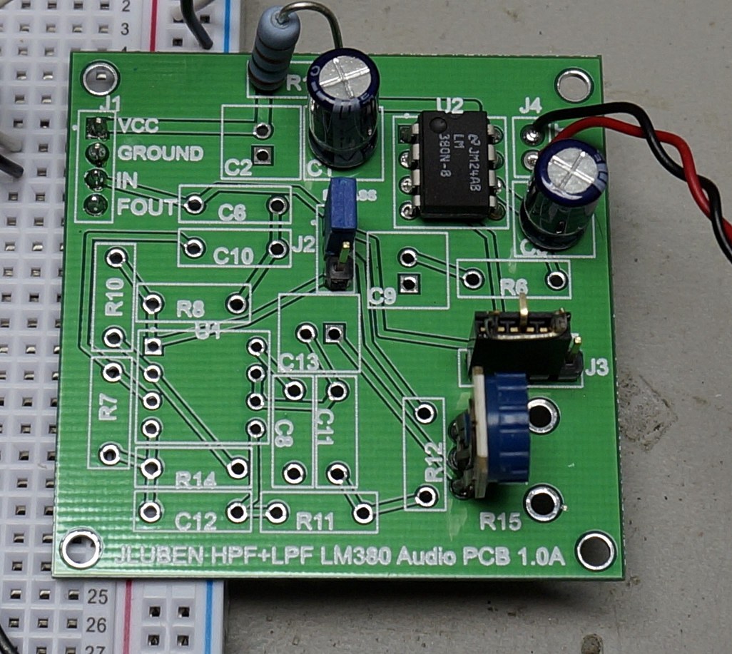
There is a minimal number of parts necessary to enable the audio amp on this PCB.
- Install U2, the LM380
- Install electrolytic capacitor C3. I used a 100uF here. You can use a bigger/smaller value if you want (changes) the frequency response.
- Install resistor R1. This can be anywhere between 2.2 and 30 ohms. This resistor should be rated for at least a half watt.
- Install filtering capacitors C1 and C2.
- If you want on board volume control, install potentiometer R15. The footprint is for a Bourns PTV09A-4020F-A103 available at Mouser for $0.70. If you use R15, then jumper pins 1 and 3 of J3.
- You can use an external potentiometer by using header J3 and pins 1 (GND), 3 (U2 input), and 4 (SIG). Feed the audio input into pin 3 of J1.
- The board has four mounting holes for 4-40 screws. There should be enough space to use R15 and mount the hold board against a panel if the headers are solder on the back of the board.