
After Jason NT7S wrote about the SI5351A clock generator, I purchased several of his Rev B designed prototype boards by Oshpark (Portland local–yeah!). I spent quite a few hours getting these things to work. The SI5351A is a msop footprint. Mounting this chip turned out to be a very tricky exercise. Every time I thought I got all the pins correctly soldered, I would go back and check with a DMM and find one that was not actually conductive.
There are a few other tricks to making the NT7S board work correctly:
- Read Jason’s documents. He has written a lot of documentation and everything is there you need to know. You just to need read it thoroughly. I did not and it took hours of troubleshooting to figure out what he already documented.
- Pay attention to Jason’s notes about using an ECS crystal. Pins 2 and 4 are connected and will short Vdd to ground.
- The SI5351A chips I got from Mouser use the I2C address: 0x6F
- Capacitor C3 on the output of the LP2985 is required to get the 3.3 volt output. Omitting it will cause the local supply voltage to be around 4 volts.
If you want a general purpose SI5351 to play with or for simple non RF purposes, the Adafruit breakout board (PN 2045) can be purchased assembled for cheaper than I can buy the parts. The NT7S board is thought out and more agile. It has better mounting holes, configurable I2C pull ups (I really appreciate this), provisions for VCXO and isolation transformers.
I really appreciate the work that Jason has put into characterizing this device. He single handed opened the doors for a lot of people to start using this device and it’s become the talk of QRP-L, EMFRD, and SolderSmoke.
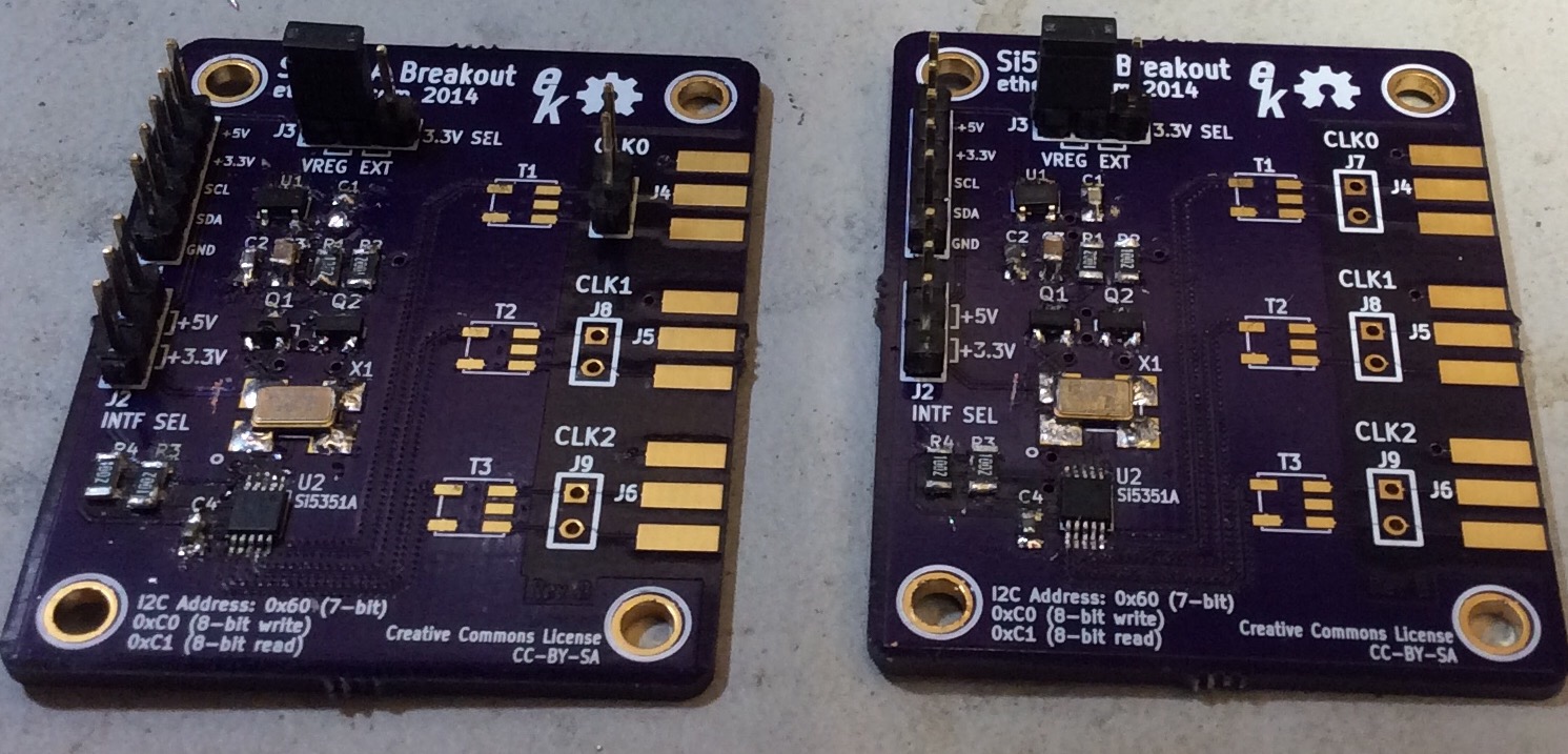
(please excuse my horrible soldering job. I had to cannibalize some SMD parts from an ActionTec router)