Build Log: M1 Transceiver: Wiring the Receiver

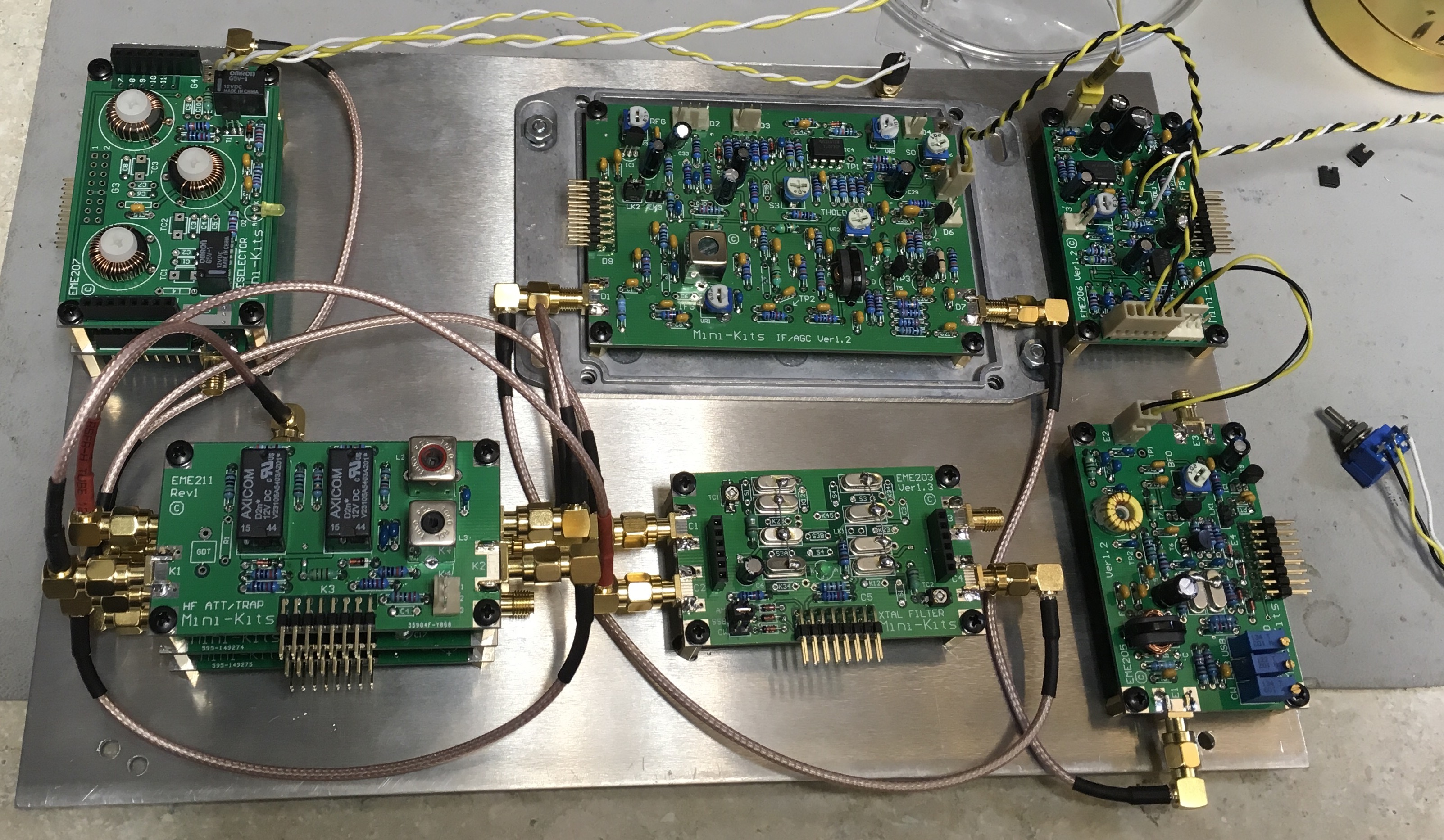
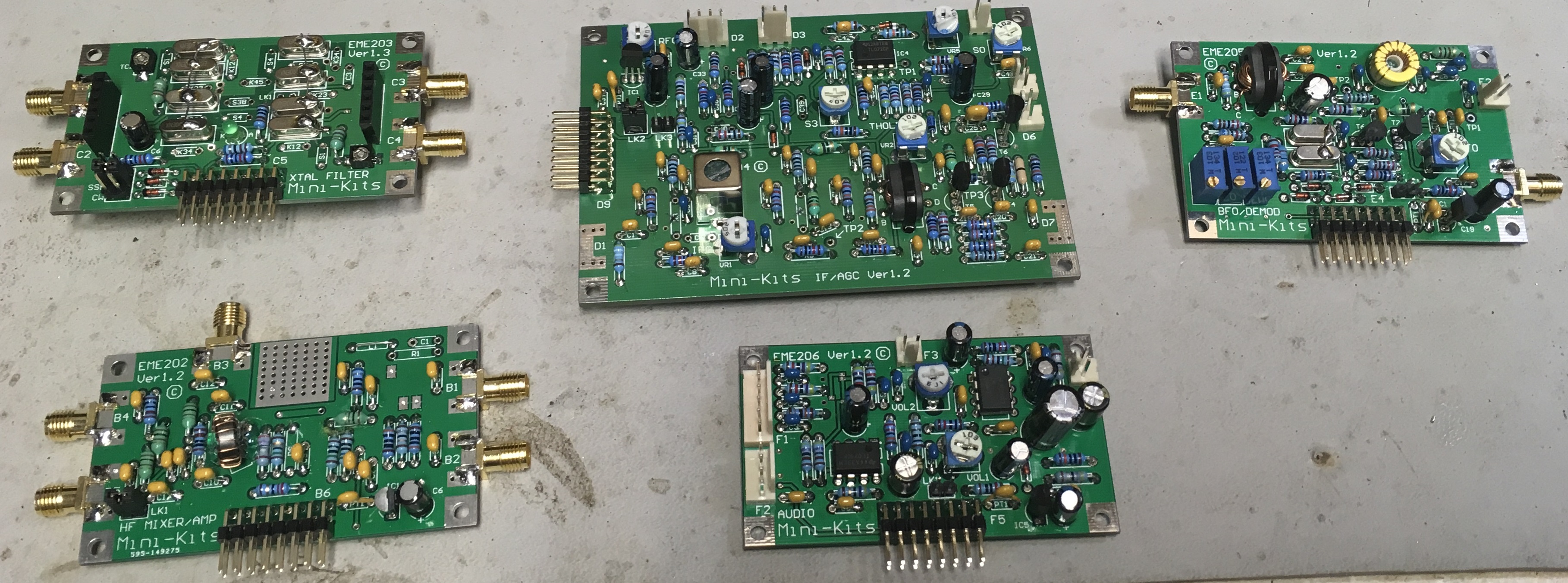
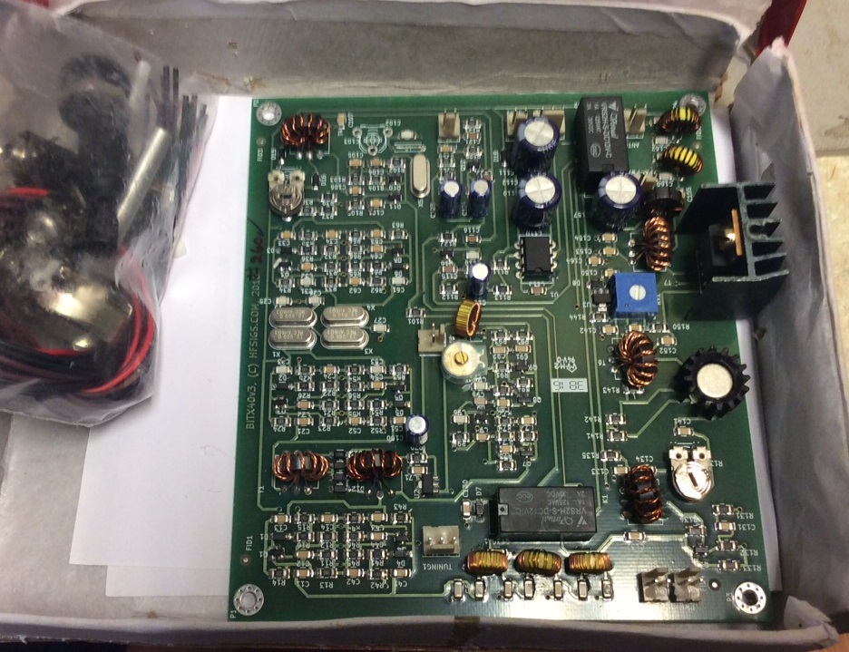
The last two days I’ve spent laying out the receiver and common IF portions of the M1. I’m basically copying the Minikits suggested layout for the Hammond case. The aluminum sheet divides the inside of the case. The common IF subsystems and receiver modules fit on the top. The DDS and modulator components fit on the bottom. A number of the boards stack.

I purchased a coax crimping tool for RG-316. All the coax jumpers are of my own creation. This cuts down the cost as those jumpers can be quite expensive for quality ones. The SMA jacks and connectors are from China. The jacks rated for a whopping 500 connections! I doubt I’ll hit that ceiling for this project.

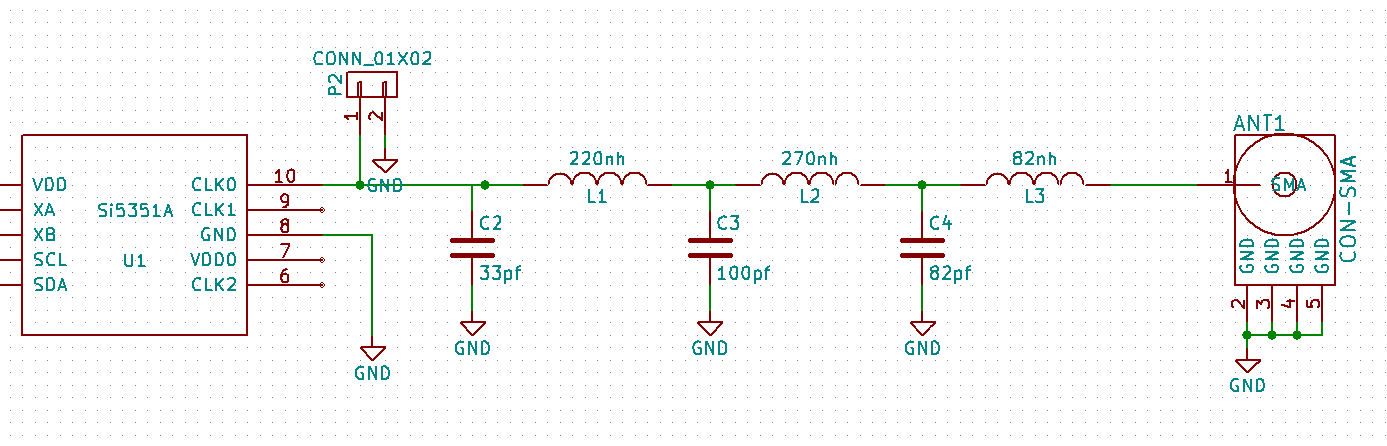
Soon, the receiver will be ready for power-on tests and alignment. The front-end mixer has a pad on the LO input, so a Si5351 at the lowest power level will be enough for to play with it.

m1 receiver

Bourns Optical Rotary Encoder PCB

I purchased a Bourns ENA1J serial rotary optical encoder. This control has a nicely weighted shaft that uses ball bearings. It is rated for >= 10 million rotations. The ENA1J outputs beautiful square signals (unlike mechanical rotary encoders). I think I paid USD$35 for this premium part. You will find optical rotary encoders on high end radios like the Elecraft K3 and professional mixer boards.

I designed a pcb that takes the quadrature output of the ENA1J into INT0 and INT1 inputs of the  ATMEGA328P mcu. A pin header gives access to the I2C bus that allows this to be used as a satellite peripheral.

encoder pcb

Build Log: Starting the MiniKits M1 Transceiver

This past summer, I ordered a MiniKits M1 modular transceiver kit. This kit packages each section onto a separate circuit board, for future modifications. Work at on1 was super busy, so I put off assembling the kit until the Christmas holiday. I did not purchase the MiniKits PIC based control and DDS system. I am going to use a si5351 with an Atmel ARM chip for digital control. I had pcbs.io manufacture a pcb with a super nice Bourns optical encoder for the main frequency dial.

The modules I purchased are:

  • EME208
  • EME207-20m
  • EME207-40m
  • EME211
  • EME209-19m-30m
  • EME206
  • EME210
  • EME201
  • EME202
  • EME203-9m-2.5k


m1 transceiver

Filtering the Si5351 Output

I’m working on building blocks that can be used for larger designs. One of those building blocks is a DDS signal generator using the Si5351. I added a low pass filter to the output of CLK0. This filter starts rolling off at 50mhz. Elsie generated the schematic and I normalized the values to smd capacitors I had and Murata rf chip inductors I purchases.

si5351 filter schematicL1, L2, and L3 are smd inductors that cost about USD$0.20 each.

Here is what the Si5351 output looks like with Adafruit’s example library sketch.

si5351 filter before2This is the output after the low pass filter. Second and third harmonics are still there, but there is definite improvement.

si5351 filter after

Panel Mounted Rotary Encoder Breakout for Arduino

I created this breakout board that enables easy use and mounting of a mechanical rotary encoder. This kind of rotary encoder suffers from debounce problems. The easiest way to address it is to put a RC network on each leg of the rotary switch. This board has mounting holes in case one ends up using encoders that do not have threads.


encoder front copy encoder back


rotary encoder schematic